Hi all -

Hope this is posted in the right forum. I am trying to figure out how to replicate subway track sparks shown on this YouTube video: http://youtu.be/9riiQdb8UUk

On his comments, he states its similar to signal block detection where a 10" track is cut with LEd lights put in place that lite when car rolls over LED.

What size LED you think is being used. How LED's are wired in order to go off and what may have been used for it to stay in place.

I'm open to anyone's opinion on helping me create this.

Thanks for any suggestions.

WP
Original Post

Replies sorted oldest to newest

What they are simulating is the third rail shoe coming off the third rail under load.  It is nicely done.  It appears that the flash occurs by a truck and only one per truck.  It is well thought out.  I do not know how this is being done, but it could be a minor truck mod to provide a contact to ground the LED once per truck.  If the trucks had sliding accessory shoes, these could be grounded to produce this effect.  

Based on his comment in the video, I think he is doing the following:


spark


He notches the outer rail (two examples shown above) making tiny "islands".  When a truck rolls by, the metal wheels and axle conduct to complete the circuit to the LED(s).  The LED power supply could be just a recycled DC wall adapter, cellphone charger, or whatever.  Or track power could be used with a dollar or so of assorted parts like diodes and resistors.  I'd think 3mm LED would work fine...on eBay they run about 10 for $1 with free shipping.

Attachments

Images (1)
  • spark
Thanks for the feedback. Stan2004 do you believe the only purpose of the notch on the track is to place the LED light in place? Would this not disrupt electrical current to other parts of the track?

Thanks for the diagram, lets say if I wanted track power how would I wire the resistor to the track in order for the truck to complete the circuit, thus causing the LED to flash?

William

If I understand your question, the notch in the track allows each wheel axle to become the "lever" (by analogy to a typical electrical switch) which completes the circuit to the LED.  It's hard to see from the video where he physically mounted the LEDs and he may have placed them in or under the gap created by a notch.  You might try asking him on youtube.


To your point, by notching the track you are breaking the electrical connection in the outer rail.  But the two outer rails are electrically connected elsewhere on your layout - probably in multiple places, at lock-ons, etc..  From the video, he says he did this on one 10" section of track as opposed to on his entire layout.  So IF the notches materially affected the performance he could have added wires (shown in purple) underneath his bed to provide outer rail continuity to the broken lower rail.  As suggested above, there are other methods which don't require notching - I'm simply taking your original question at face value and speculating on how the youtube version works (and quite well I think!).


What kind of track do you have?  One nice thing about 3mm LEDs is a 1/8" drill bit might be all you need to make mounting holes.


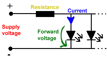
As for using track power, it can be as simple as the following.


spark-1


The diode converts the AC to DC since LEDs run on DC.  The resistors limit the current to the LEDs.  The value of the resistor depends on what kind of track power you use (command, conventional).  If you use conventional the brightness of each LED will be proportional to track voltage which is probably not a big deal...or with some additional circuitry such as a voltage regulator you can take care of that too.  In any event, I'd think all the electrical parts would fit in the cavities underneath one track section if you use, say, MTH Realtrax.


I think the biggest hurdle is to take the mental leap of faith that this can be done!  I think it might take a few tries requiring some sacrificial track sections and there are some additional electrical details that need clarification but that's what the OGR forum is about!  There are several guys on the Electrical Forum who would also have ideas if you do choose to proceed.

Attachments

Images (1)
  • spark-1
Originally Posted by Joe P:

I commented to the YouTube poster about the block occupancy design.  I think these are blinking LEDs.  The only problem is that the LEDs will blink continuously if the train stops in the block.

The youtube guy says he uses "flashing" LEDs.  You can get them for about 2-3x the price of regular non-flashing LEDs on eBay.  Hopefully he will provide additional info but I think he does this to somewhat randomize the simulated sparks so they don't all look the same.  That is, for a train going at some fixed speed each wheel will hover over an "island" for roughly the same amount of time meaning the flash will last the same.  Techniques such as different-sized islands, flashing LEDs, non-constant LED supply voltage, etc.. seem like possible candidates to vary each flash.  With a few more electrical parts, each LED could be made to flash just once when the wheel enters an island so there would be only one flash even if the axle stopped on the island.

Sorry for the late reply, I didn't know the link was to one of my videos. There are a lot of ways to do this I did the easy route. I use MTH realtrak but it can be done on any track system. Some experimenting will need to be done to get the effect you want. The LED's that I used cool white 1.8mm from Evans Designs. They are alittle prices but all of the wires, resistors, diodes, etc.. are already build in so that eliminates a lot of wiring plus they work with ac or dc power supply. I used a 10in track section MTH model #40-1029. http://www.mthtrains.com/content/40-1029

You can use any track you want but this one requires no cutting of the rail.


IMAG0034 [2)


IMAG0035 [2)


The track comes in two 5in sections that are cut down the middle to give you 4 sections at 2.5in in length which is about the size of one subway wheel truck. Removing the wire on the bottom of one of the outside rails will isolate that section of track from the rest of the system. That is where one wire from the led goes, the other is connected to the hot or center rail.


IMAG0036 [2)

In this pic the top rail is isolated for the LED to flash when the train rolls over this section. Also more step may need to be taken to prevent the LED from lighting up at the wrong time or staying lit when the train has passed. In this case the copper clips that connect the track together are removed (only on the isolated rail and not the copper clips holding the white wire in the 2nd pic) and use small pieces of plastic or postcard to slide in between the rails to prevent contact. If you like real close you can see the plastic in between the joints. The LED is a 1.8mm flashing light and should fit in between the top and bottom of the rail. I moved the led out so you can see it. There are two downsides to this.


1. If you have other thing going on your layout, crossing gates, signal lights, a lot of switches and double crossovers. Adding some of these could mess with you DCS signal

if you are using DCS to run your trains.

2. If you stop the train and one of the wheels/truck is on the isolated track the LED will keep flashing. There are ways to prevent this but I didn't go through all the trouble because my trains only stop at stations.

Any track system can be used, You will either have to cut the rails or buy smaller track sections and isolate one rail on that section. I used this method on a O-31 1/2 curve.

Attachments

Images (3)
  • MTH Realtrax
  • MTH Realtrax
  • Realtrax
Now that the inventor has confirmed how he did it, I was inspired to experiment with this special-effect even though I don't run subways!


I don't have the short track sections he used so after initially trying to cut an outer rail with a hacksaw, I gave up and used a bandsaw to cut from the edge to make two outer-rail isolated islands - I figure some putty and gray paint could touch up the bed if need be.  3mm cool-white LEDs are installed from the bottom through 1/8" holes.  With a diode attached to center-rail and 1 resistor per LED taking track power as previously diagrammed, here's a short video with a streetcar which is closest thing I have to a subway.


spark-fun-top

spark-fun-bottom

Attachments

Images (2)
  • spark-fun-top
  • spark-fun-bottom
Videos (1)
spark-fun
Originally Posted by stan2004:
Now that the inventor has confirmed how he did it, I was inspired to experiment with this special-effect even though I don't run subways!


I don't have the short track sections he used so after initially trying to cut an outer rail with a hacksaw, I gave up and used a bandsaw to cut from the edge to make two outer-rail isolated islands - I figure some putty and gray paint could touch up the bed if need be.  3mm cool-white LEDs are installed from the bottom through 1/8" holes.  With a diode attached to center-rail and 1 resistor per LED taking track power as previously diagrammed, here's a short video with a streetcar which is closest thing I have to a subway.


spark-fun-bottom


What does the value of the resistor have to be for the LED? idk what amount to get or how to figure out the right resistor

I couldn't find the 3/15/13 video mentioned above (does anyone have a link?) but I found the following which shows the Ace Trains E/17 "sparking".  The sparking starts midway at about 1:49 as shown on the video time-stamp in the photo below.


http://www.youtube.com/watch?v=BR90rJXt8yk


I pasted in a photo from the Ace Trains website showing the sparking unit on the underside of the trucks.  From the video, comparing the sparking "color" to the headlight color it looks like they used blue LEDs. 


ace trains maybe blue LED 

If blue is your preferred color, "3mm blue LED" are the same cost (10 for $1) as white on eBay.  Same circuit.  Or a dab of clear-transparent blue paint could be applied over a white LED to add some blue to the flashes.  Animated garage-workshop dioramas often use a mix of LED colors (white, blue, orange) to simulate the welding sparking.


Attachments

Images (1)
  • ace trains maybe blue LED

So in theory if I hook up a 9 Leds in a parallel wont it just be enough? im confused because I used the LED calculator and it said if I hook up 32 Leds in parallel and each take 3.2 volts, I would only need a 20 ohms resistor.
As for the train interior, I was going to remove the incandescent blubs and just put in like 3 white Leds  to make it look more brighter and prototypical. Last question, what did you use the cut the track? Thanks again!

Not sure what you mean by 9 LEDs in parallel being "enough".  Enough for what?


As for 32 LEDs in parallel, I can't imagine any subway car holding that many LEDs!  If you have 32 LEDs each drawing 20mA @ 3.2V, that's a whopping 0.64 Amps of current.  A 20 ohm resistor would drop 12.8 Volts but in doing so would become quite the heater; Power = Volts x Current = 12.8 V x 0.64 Amps = 8.2 Watts.  You'd need, say, a 10 Watt resistor which would probably melt something in the car.  That's a lot of wasted heat considering that the LEDs themselves would only be consuming 3.2V x 0.64 Amps = 2 Watts.  When a circuit draws this much current, you would use other techniques (instead of a resistor) to control the current/voltage into the array of LEDs.


If by removing bulbs you mean to somehow insert 3 3mm LEDs (plus resistor) in each location where there's presently a bulb, then OK.  You'll have to experiment a bit since the 3mm LEDs you mentioned have relatively narrow beams (about 30 degree) while an bulb projects in all directions.  If you search the forums for LED passenger car lighting you'll see dozens of threads on the virtues of so-called LED strip lights which run at about 10-12VDC.  These are nice because they have wide-angle projection for more uniform illumination


I cut the track using a metal-blade bandsaw.  As mentioned earlier I tried to cut just the outer-rail with a hand hack-saw but couldn't get the right angle or orientation...so ended up slicing the trackbed itself to get to the rail.

Opps, I meant 32 Leds to light up the "Subway" Part of my layout. As for the train, I will simply experiment with the 3 LEDs as you have said. I will probably use 1.8mm for the subway LED lights. A parallel layout looks like this

So I guess one Lionel CW-80 cant power 32 1.8mm Leds?
I have heard of LED strips also but im not sure how much resistance I will need for a particular strip of LED

Last edited by nycboy

For the constant-on tunnel illumination with 32 (or whatever many) LEDs, I recommend a DC-DC converter module.  Otherwise, as discussed above, when starting from a "high" voltage like 18 V and dropping (via resistor) down to 3V, most of your power is going up as heat in the resistor.  A DC-DC converter module uses switching circuits to more efficiently convert the power from one voltage to another so you don't waste power as much power. 


ogr lm2596 ac-dc

Search eBay for "LM2596 module" and you'll see these for 99 cents and that includes shipping!  It's an extremely good value.  You can buy versions that have a bridge rectifier already installed on-board ("LM2596 AC module") but they are more expensive considering you can buy a bridge rectifier for $1 or so on eBay (any bridge rated for at least, say, 2 Amps and 100V).


So you apply AC from your CW and adjust the module to put out some lower voltage like, say, 3.5V to drive a parallel string of 32 or however many LEDs.  In this case the resistor will be a much smaller value so the power it wastes as heat will be much smaller.  If you have an unused 9V, 12V or whatever wall-adapter with DC output, you can skip the bridge rectifier as you already have DC.  You will need a voltmeter to adjust the output voltage but as I was advising a guy in another thread you don't need a fancy meter and Harbor Freight Tool stores if you have them in your area give these away free (with coupon) shown here being used to adjust the module output to 3.0V which is what he wanted to drive a string of a parallel LEDs.


ogr hf meter 3v

Speaking of parallel LEDs, this reminds me of another freebie I picked up at Harbor Freight - a small 4.5V operated LED worklight that has 24 parallel LEDs. 


ogr harbor freight worklight

All those white LEDs are wired up in parallel just as you're planning to do...and note they use a 1.5 ohm resistor.  But this is, in part, because they are starting from about 4.5V (3 1.5V batteries).  If you choose to use a DC-DC module where you can precisely set the output voltage (the voltage output is regulated so you set-it-and-forget-it), you really don't need a resistor at all if you are driving all like LEDs.

Attachments

Images (3)
  • ogr lm2596 ac-dc
  • ogr hf meter 3v
  • ogr harbor freight worklight
Originally Posted by nycboy:
did they buy the IC chips or they made it them selves? Curious cause if not ill just have to fiddle around with the extra resistors then

All the stuff being done on OGR is with purchased IC chips (generally inexpensive at, say, 50 cents each).  The LED for Dummies thread below started off as a simple "for dummies" thread but morphed into a smorgasbord of ideas about everything under the sun including comparing LED strips vs. individual LED (as you are considering).  You can get a flavor for the kinds of IC chips being used and determine for yourself if you want to go there. 


https://ogrforum.com/topic/leds-for-dummies

I must say, Thank you stan for all the information you provided! you taught me almost a semester worth of information at my college. So Change of plans, Heres my Idea, this is for the constant LED illumination (32 in the subway)


I get any sort of DC 5V or 12V wall adapter laying around my house, Strip the wires, Screw them into the LM2596 (The one I see on ebay has a built in voltimeter) I also noticed it has a USB port..Any reason to why it has it?
http://i.ebayimg.com/00/s/NjAw...OxyMt5TJ8Gu/$_12.JPG

After wards I set the volts to say 3.2V output, and then from the output of LM2596 I just add the wires to the output and simply do the parallel set up I was talking about, and since its already at 3.2v, I wont have to use any resistors on it.

I dont think ive asked this, But I do plan on using DCS in the future, But whats the point of getting an inductor? 


As for the LED Strips, Ill look further into the thread you have provided me.

Thanks again for all your help Stan, Once I recieve my LEDs and resistors I ordered Ill post some pictures here if I get them working correctly.


Last edited by nycboy

This will be on the test so...


I hooked 12V DC to a LM2596 modules w/voltmeter to the worklight LED array of 24 bypassing the resistor to directly drive 24 parallel white LEDs (5mm diameter).


ogr hf woklight 24 led

You will probably get similar results and will probably find you can operate closer to 3.0V.  If you're a student, here's that sharp diode-junction "knee" or hockey-stick on the V-I curve in action which is the first curve they always show in the chapter on semiconductors.  That is, note the small changes in voltage having an outsized effect on current going from 2.8 to 3.0 to 3.2 Volts.  For example, going from 2.8V to 3.0V (delta of 0.2V) causes the incremental current per LED to increase about 7 mA.  Use Ohm's law and you get the dynamic resistance of the LED at that operating point...much smaller than the average resistance of the LED.  Hmm, I hope they teach you about dynamic resistance and load-line curves!


The big win with switch-mode regulators is conversion efficiency.  So at 3V, the 24 LEDs pull 0.3 Amps or ~0.9 Watts.  At that output voltage, the 12V input current was 85 mA or ~1.0 Watt.  So the efficiency (power out/in) = 90% which is very good for this type of power converter.  Actually a little power is being consumed by the voltmeter circuit but can be ignored for this example.  If you used the resistor method, the current in and out is the same.  So for the same 0.9 Watts out, the input power would be 12V * 0.3 Amps = 3.6 Watts.  The conversion efficiency would be 25% which is not so good as 75% of the energy is wasted as heat.


I have no idea why there's a USB connector on your module. I found an eBay listing that looks like your module and one photo shows the USB connected with the voltmeter at 5.0V.  So perhaps this is meant to be a USB charger...though it seems pretty risky to require a user to set it to 5.0V before using it as a charger?!  Anyway that's my guess.


WRT to DCS signaling, the inductor isolates the impedance (not resistance) of the capacitor from the track voltage.  The DCS signal rides on (in class they'll say "super-imposed on") the low-frequency 60 Hz track voltage and is hi-frequency in the kHz-MHz range.   A capacitor's impedance is inversely proportional to frequency so it tends to load down the DCS signal.  An inductor's impedance is proportional to frequency so by placing it between the track and the circuit, it demotes the loading while still allowing the power signal to reach the load.


Separately, your tunnel photo shows lights on each side of the track.  Rather than a single long string of 32 LEDs, run two strings of 16 each (or whatever) from the converter output.  This cuts the max current running down each string in half which is beneficial for voltage drop effects as well as wire heating though with the current levels involved you probably won't see any effect.

Attachments

Images (1)
  • ogr hf woklight 24 led
Last edited by stan2004

If you're referring to the effect on DCS signaling, then you don't need the inductor.  The problem for LED lighting is you will see flicker.  Incandescent bulbs kind-of sort-of demote the flicker effect since there's a filament time-constant where the bulb brightness decays (albeit quickly) when voltage is removed.  The common wisdom has been that since the inductor cost is negligible relative to the effort to open up a car, re-wire, add LEDs, etc., why not just throw in the inductor even if you don't use DCS today.

Originally Posted by stan2004:

If you're referring to the effect on DCS signaling, then you don't need the inductor.  The problem for LED lighting is you will see flicker.  Incandescent bulbs kind-of sort-of demote the flicker effect since there's a filament time-constant where the bulb brightness decays (albeit quickly) when voltage is removed.  The common wisdom has been that since the inductor cost is negligible relative to the effort to open up a car, re-wire, add LEDs, etc., why not just throw in the inductor even if you don't use DCS today.

Guess Ill have to order some capacitors and inductors. what should be the F and the Volts on them? Does it matter  if I get a strong capacitor or strong inductor (I.e Holds in a larger amount of charge)

As shown earlier, MTH uses a single 47uF, 35V capacitor for the 2 red marker LEDs in a passenger car.  As you add more LEDs (such as converting the interior bulbs to LEDs), more capacitance is needed as there is more current drawn during the dropouts.  Everyone's situation is a bit different wrt how clean you keep your track, tolerance for flicker in the first place, number of turnouts, etc., but I'd say the typical values that the guys use when there are a bunch of LEDs would be 220 uF, 35V (or 50V).


The inductor used for DCS in passenger cars is 22 uH, 1/2 Watt. 


Now in class they talk about energy storage in an inductor and capacitor.  But in this case the inductor is used for its complex-impedance to block hi-frequency signals, not for its energy storage.  Your textbook tells you the stored energy (in Joules) for an L (in Henries) or C (in Farads) is 1/2 * L * I^2 and 1/2 * C * V^2 respectively.  Seems about the same right?  Well, let's look at some real-world numbers for a subway car.  Let's say the current flowing to drive the LEDs is 50 mA total.  And the voltage available to charge the cap is 18V.  A 22 uH inductor with 50 mA flowing stores only 27 nanoJoules of energy.  A 220uF cap charged to 18V stores 35 milliJoules of energy.  The cap stores 1 million times more energy.


Originally Posted by stan2004:

As shown earlier, MTH uses a single 47uF, 35V capacitor for the 2 red marker LEDs in a passenger car.  As you add more LEDs (such as converting the interior bulbs to LEDs), more capacitance is needed as there is more current drawn during the dropouts.  Everyone's situation is a bit different wrt how clean you keep your track, tolerance for flicker in the first place, number of turnouts, etc., but I'd say the typical values that the guys use when there are a bunch of LEDs would be 220 uF, 35V (or 50V).


The inductor used for DCS in passenger cars is 22 uH, 1/2 Watt. 


Now in class they talk about energy storage in an inductor and capacitor.  But in this case the inductor is used for its complex-impedance to block hi-frequency signals, not for its energy storage.  Your textbook tells you the stored energy (in Joules) for an L (in Henries) or C (in Farads) is 1/2 * L * I^2 and 1/2 * C * V^2 respectively.  Seems about the same right?  Well, let's look at some real-world numbers for a subway car.  Let's say the current flowing to drive the LEDs is 50 mA total.  And the voltage available to charge the cap is 18V.  A 22 uH inductor with 50 mA flowing stores only 27 nanoJoules of energy.  A 220uF cap charged to 18V stores 35 milliJoules of energy.  The cap stores 1 million times more energy.


Sorry Stan but I got a question, You said before that when you put in the diode to the middle rail, It will reduce the voltage by half, are you sure this is correct? Ive read about voltage drop but i haven't read a topic that says a Diode will reduce the voltage by half

Originally Posted by nycboy:
Sorry Stan but I got a question, You said before that when you put in the diode to the middle rail, It will reduce the voltage by half, are you sure this is correct? Ive read about voltage drop but i haven't read a topic that says a Diode will reduce the voltage by half

No worries.  For model train electronics there a two relevant characteristics of a diode.  One is they conduct current in one direction which effects AC to DC conversion.  The other is they induce a voltage drop of about 0.7V.  Note that there are interesting applications for diodes in communications for shifting frequencies of signals or switching RF signals but we're talking model trains.


For the sparking application, by inserting a single diode as shown earlier, the current only flows on half of the AC line cycle.  Look up "half-wave rectification" in your textbook.  Then, because voltage is only available to the LED half the time, the effective voltage is cut in half.  IF instead of a single diode you used a bridge rectifier, then current could flow on both halves of the AC line cycle and the voltage would not be cut in half.  This would be "full-wave rectification".


In the sparking application, there is NO capacitor shown.  If you inserted a capacitor after the diode, this would store energy during the intervals when there would have been no available voltage.  So during the half-cycle when the diode could supply current to the LED, it would also charge up the capacitor.  During the other half-cycle when the diode was "cut-off", the capacitor would step in and supply current to the LED.


You might need to think about this for a bit but you don't want to install capacitor in a sparking circuit for 2 reasons.  First, if you are using track power, then the capacitor means you need to also add that inductor to deal with DCS signaling.  Second, by leaving out the capacitor, the voltage available to the LED is more "choppy" and variable (the capacitor smooths the voltage).  You want this somewhat random-like change in brightness in the LED for sparking.  Note that the inventor even used a "blinking" LED presumably to make the sparking more random or hence more life-like (in my opinion).


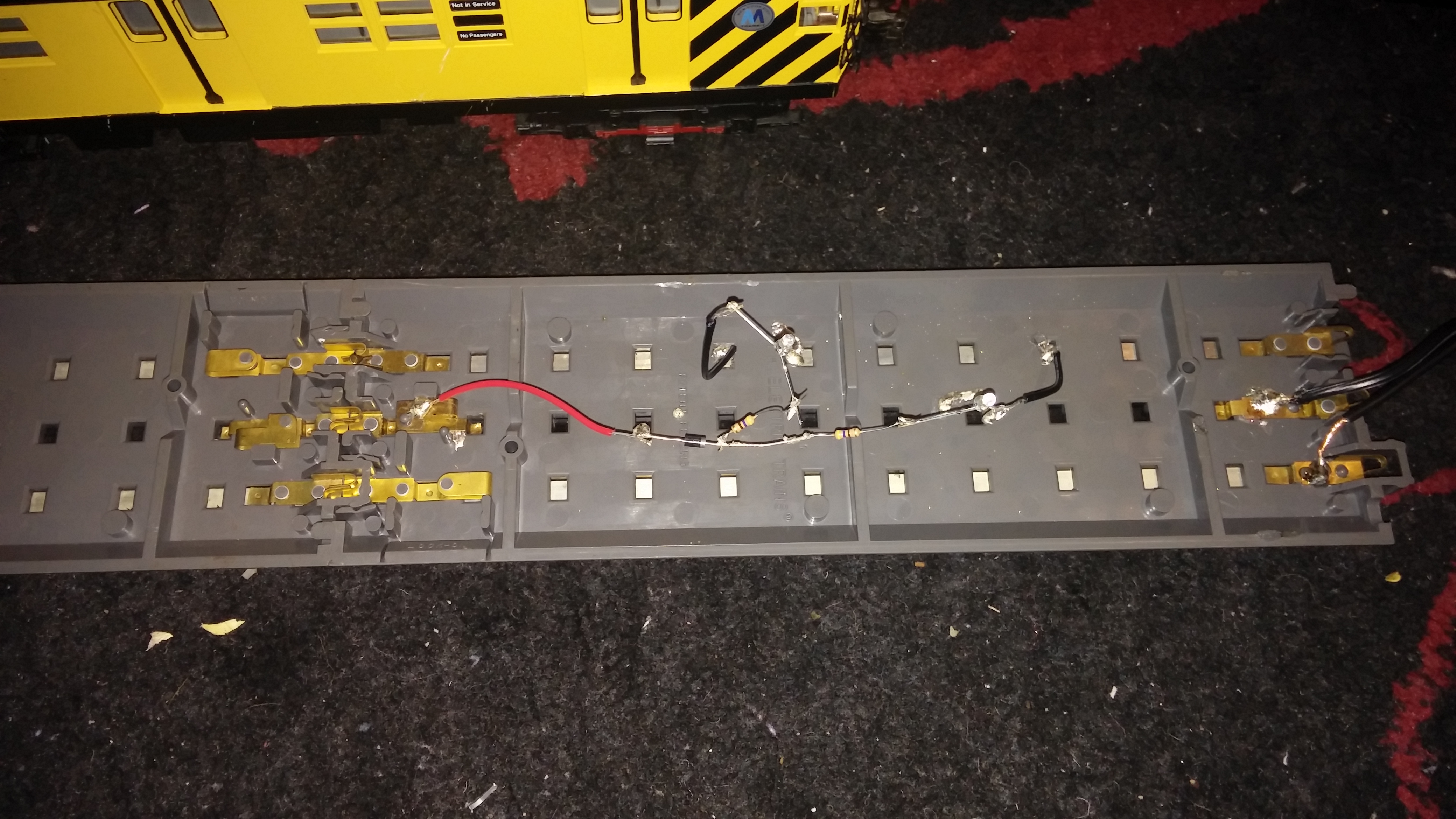
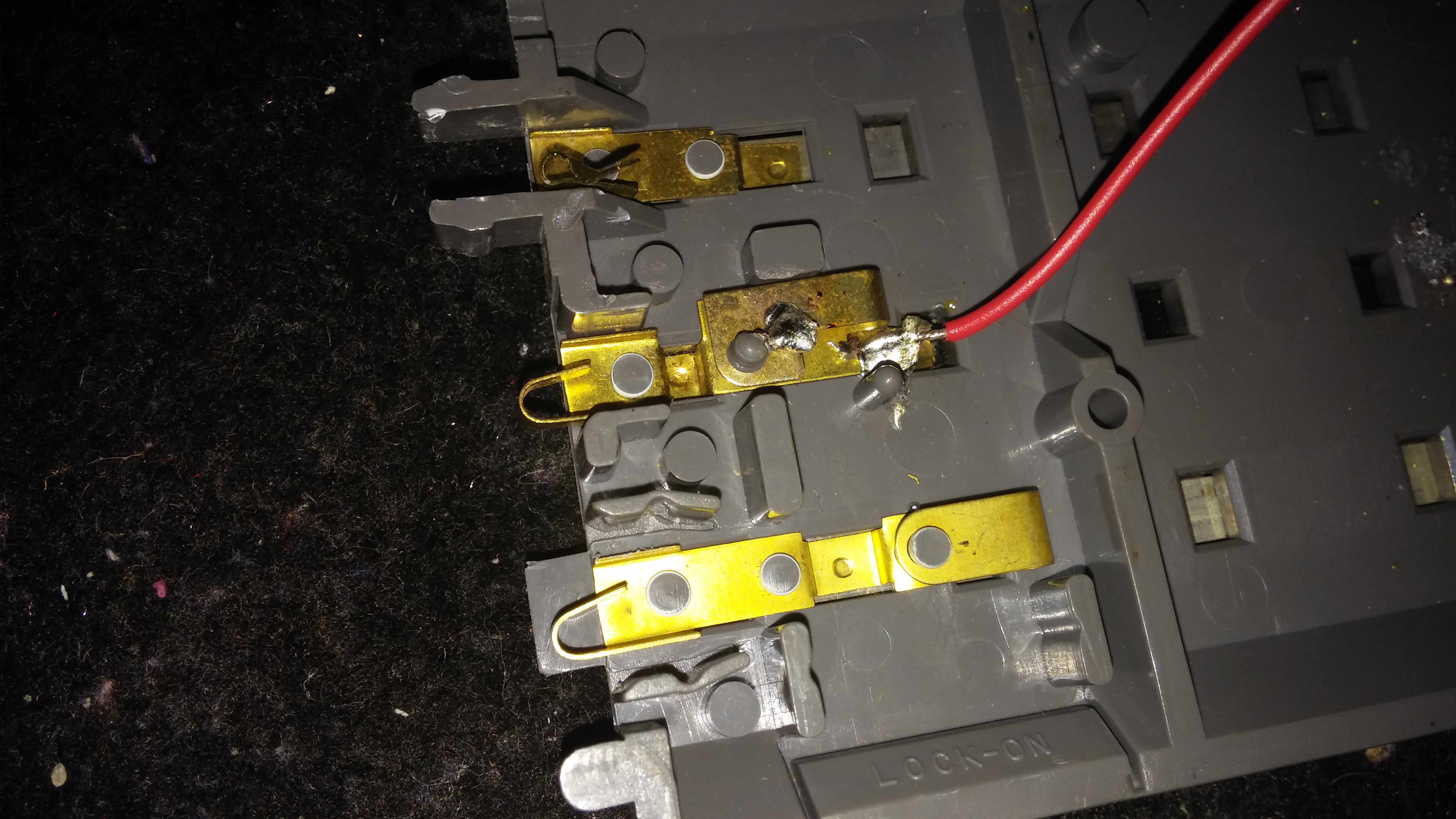
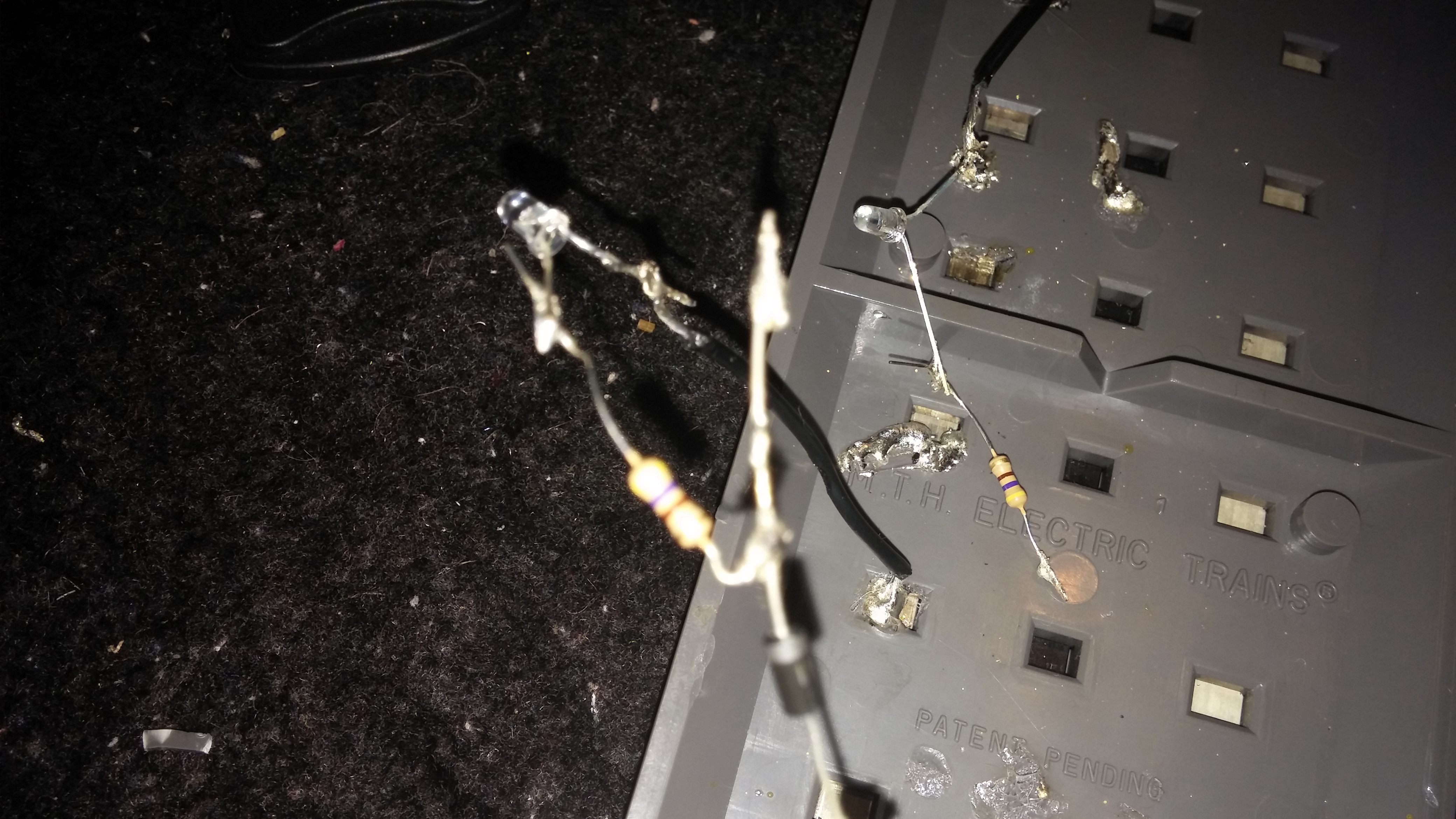
ahhh..Bad news it failed! The LEDs did not light up. I tried to resolder everything moved the hot wire but it still failed. Im not sure why. Im using the 1N4007 1A 1000V Rectifier Diode DO-41. important thing note is I did not cut the rails because I dont have a hacksaw handy, instead I just bent one of the connectors out of place. When I put power and the train on it the LEDs did not light up! I put it another LED with a 1k ohm resistor and still it did not work.  Im using the Lionel CW-80 and mth reatrax.

20140430_180213 by [url=https://www.flickr.com/people/32235547@N02/]killa134528[/url], on Flickr

20140430_172452 by [url=https://www.flickr.com/people/32235547@N02/]killa134528[/url], on Flickr

20140430_180055 by [url=https://www.flickr.com/people/32235547@N02/]killa134528[/url], on Flickr

20140430_180105 by [url=https://www.flickr.com/people/32235547@N02/]killa134528[/url], on Flickr

20140430_180114 by [url=https://www.flickr.com/people/32235547@N02/]killa134528[/url], on Flickr

20140430_180155 by [url=https://www.flickr.com/people/32235547@N02/]killa134528[/url], on Flickr


Originally Posted by stan2004:

You should be able to run a "red" and "black" wire direct from the CW to your red and black wire and the LED should light up.  Also, do you have a voltmeter handy?

I ordered a voltimeter, hopefully it will come soon so I can ese what the issue. I will probabl trying tfixing this again idk how though

Last edited by nycboy

Add Reply

Post

OGR Publishing, Inc., 1310 Eastside Centre Ct, Ste 6, Mountain Home, AR 72653
800-980-OGRR (6477)
www.ogaugerr.com

×
×
×
×
Link copied to your clipboard.
×
×