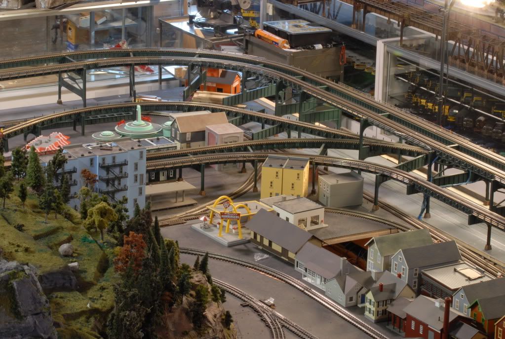
I am working on an elevated track section of my layout. I am using 1 x 3 clear section pine for the bridge base structure. with mitered cross beams in artist plywood for the cross supports, I use 3/8 square wood for the risers. I will post some pictures.

Question becomes as I create a curve over another curved, and that track hovers over it, how do I construct that radius so the base structure bridge base looks the same?

I could cut a plywood curve but what thickness of plywood would I need?

I was thinking about mitering the 1 x 3 but then I need some sort of fixture to create the curve...its a flex track curve as well.


Bridge Boss has some nice track supports but I need clearance to the track below. so the support and bridge support can only be 1 inch below the upper track.


So my first step is to research some pics on the net.


fig14-8

img_114437

images [4)


166y5ty

images [3)


ny_9th_ave_el_001

3630596960_a87762e28f_b

NYC_Elevated_RR_110thSt

suicidecurve1

Attachments

Images (11)
  • fig14-8
  • img_114437
  • images (4)
  • El_station_010
  • 166y5ty
  • images (3)
  • Gulf Curve
  • ny_9th_ave_el_001
  • 3630596960_a87762e28f_b
  • NYC_Elevated_RR_110thSt
  • suicidecurve1
Last edited by J Daddy
Original Post

Replies sorted oldest to newest

John, looking great.  There is one other technique.  It's called "spline roadbed".  The other scales frequently use this.  Have not seen it much in O scale.
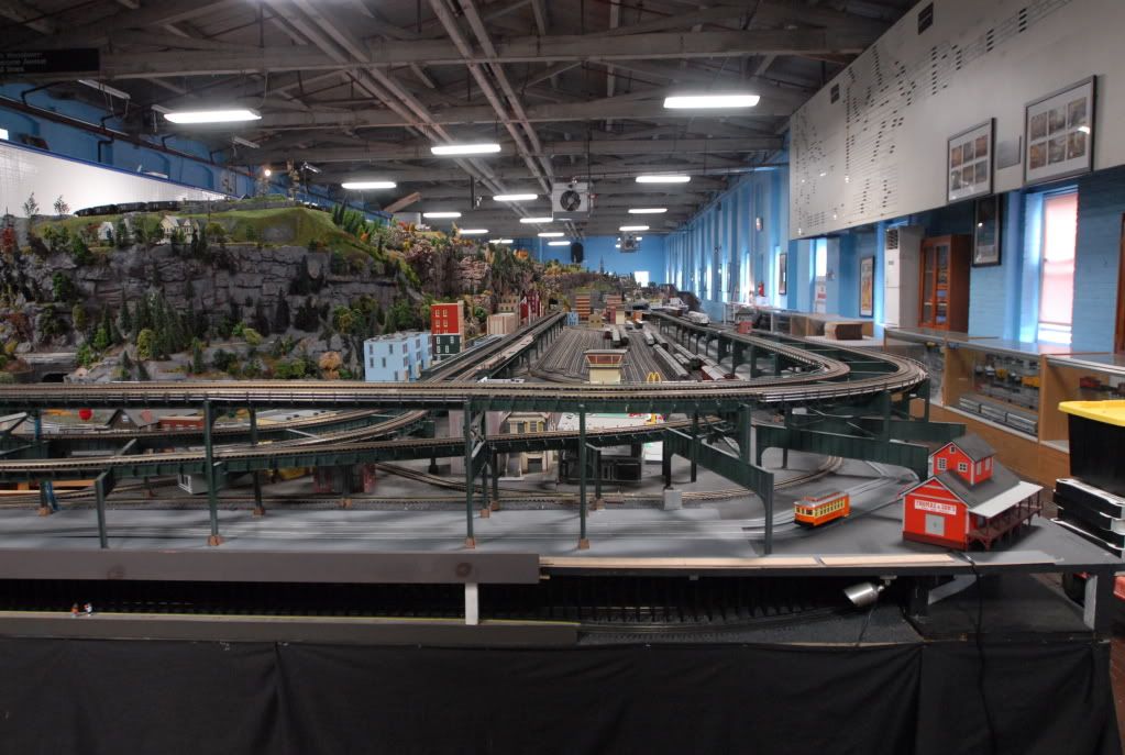
Google search Model Railroad Spline roadbed to get many examples.  

You could use a small spacer instead of solid road bed.  Some use this technique to avoid the wood warping over time.

Dan

I can see why it takes us so long to complete a "train" project.

Last night all I could do was run trains on the new structure!

Something about the Lincoln top Hat on this engine...

20150105_224212 [2)

20150105_224344

20150105_224208

20150105_224212


This shot shows the curve I need to start focusing on: Notice the trio of American flyer accessories that will need to find a new home. Hard to get rid of them when your Dad had them and gave them to you when you were a kid...


20150105_224250


Here is a couple more shots of the North End of Highland Yard.


20150105_224144

20150105_224316

Attachments

Images (7)
  • 20150105_224212 (2)
  • 20150105_224344
  • 20150105_224208
  • 20150105_224212
  • 20150105_224250
  • 20150105_224144
  • 20150105_224316
Originally Posted by loco-dan:

John, looking great.  There is one other technique.  It's called "spline roadbed".  The other scales frequently use this.  Have not seen it much in O scale.

Google search Model Railroad Spline roadbed to get many examples.  

You could use a small spacer instead of solid road bed.  Some use this technique to avoid the wood warping over time.

Dan

Good Point Dan,

I have used this technique on a few curved deck bridges. I  have a had good success with this when the bridge abutments can be fixed and the lengths of the decks and be cut and curved. the abutments help hold the structure in place so it can dry... but this one has to have a pre-made radii, then suspended... that's where I was thinking of making a wood fixture...

Thanks for the compliments.

Right now I am tackling the 100 and 96 inch elevated radius.


The tough thing is drying time. And clearance for a big boy below on the radial tracks.


I prebend the radius of gargraves, then mitre cut each base wood structure (1x3 milled to 1x2) by approximatley 10.5 inches in length. then add the inner radii base wood structure and mitre it so the supports spans are parrellel. I am not a math major but each angle on the mitre was alternating ends 3 degrees, and 6 degrees, seemed to work out best.

It takes one day for each section to dry in its clamps. 3 down, 7 more to go...

Good news is if you have any variation in up down on the tracks it can be eliminated by clamping in each section and securing the track to the wood base sections with screws.

The overall track height surface parellism is controlled with a 3 ft level.


I will post some pictures.


Tom,

I think the three A/F structures will be displayed on a shelf for the "begining days" of my memory of trains. One day I'll get the needle for that talking station... That record and its recording I really miss.

Thanks again guys...


Checking clearances is a must...

I am using 21.5 inch Atlas cars, and a Captain High Pockets K line caboose with radio antenna as my worse case checks, until I can break out the Layout killers.... The Bigboy, Vision line Challenger, and "The Beast" ( the PRR S1 Duplex)...

Radii are approximately 100 and 096 respectively...


20150122_220604

20150122_220457

Attachments

Images (2)
  • 20150122_220604
  • 20150122_220457

John, this is a good day indeed!  I found two topics on building your upper level!!


it is looking great!  I really like how you are building a prototypicaly correct (as much as possible), you are involving your kids, and you have something your young son loves, which I saw a day or two ago!  Excellent family project!  Oh yes, you are including your American Flyer accessories that your dad owned!  It's great!

Thanks guys need the cheer section to keep things going sometimes.

Here I cheated and bought some clamps to help my process time go up!


And just when things started to look good I threw a curve switch cross over in there just to spice things up... hmm a radial cross over switch -cross that one off the bucket list...


20150124_184252

20150124_195602

20150124_232643

20150124_232624


20150124_232624 [2)

20150124_184315


Here the top brass in the Club car are checking out the new cross over...


20150125_214401 [2)

Attachments

Images (7)
  • 20150124_184252
  • 20150124_195602
  • 20150124_232643
  • 20150124_232624
  • 20150124_232624 (2)
  • 20150124_184315
  • 20150125_214401 (2)

Add Reply

Post
×
×
×
×
Link copied to your clipboard.
×
×