I'm looking at a roughly 3.8% grade on my layout to get from the top level to the bottom level. The full length of the elevation run is about 51.54' and the rise is supposed to be 2'. We'll see. That 50' section is broken into segments A B and C. "A" has gentle curves accomplished with flex track. "B" is a 72" half circle. C is the final straight stretch to the upper level. 

My question is how much can I reduce my chance of string lining by banking my curves? I know some of the curves are banked on tracks I've seen near me but I don't know how common this is in model railroading or if it's even possible/effective. 

For the record, as far as operations on a grade like that, I'm open to splitting the train like they did on Saluda Grade but I suspect I'll be able to get away with running one complete train if I use helper locomotives. I'm actually pretty excited about the second option because I think it will create a cool operation scenario. 

Original Post

Replies sorted oldest to newest

I would love to see a sketch showing the general layout of your train room, and your track plan.

A 3.8% grade is almost too steep to be "scenic" on a model train layout.  There's a risk that it will look forced.  Two feet is a lot of height difference.  So my first instinct would be to surrender 65 sq ft of floor area to a dedicated helix.  I'm pretty sure the grade inside the helix wouldn't be as steep, and it would allow your trains to move between levels with fewer operational problems.

How long are the trains that you're planning to run?  3.8% is steep, and with varying curvature you're inviting trouble.  In order to reduce stringlining with all the power on the head-end, you would have to bank the curves OUTWARD.  I can't recommend this.  The first time your loco loses its command signal (or if a loco without cruise control uncouples from it's train) it will launch itself from the track!

Others will tell you to always put heavy cars at the front, etc.  Depending on your operating style, prototype operations, etc., I find this line of thinking very limiting.  So my advice is to reduce the steepness of the grade, broaden the curves, and/or run shorter trains.

A helper grade is great fun if you have two operators.  It might be tough to run both locos "hands on" yourself.  Having the lead loco on cruise control probably helps a lot.  If you're determined to integrate a helper grade into your layout, you should probably add a little weight to the bottom of most of your freight cars.  Most modern locos with rubber tires have enough tractive force to pull any load on their own; as you surmised the issue is stringlining.  So a very gentle push at the rear is all that's needed.   The helper ends up being more for show than actual necessity.  My $.02.

Banking curves on a railroad is a lot diferent then on a model railroad. Real railroads do it to keep the train on the track at a high speed. I did a 33' foot rise to go 6 inches. Mine was a sweeping S curve with 0-80 preformed curves. I think you would run into more of a problem of stringing if you bank the curves. You would be working with 2 factors, one the rise and 2 the weight of the train going up. Banking could cause the train to fall to the inside of the curve.....My thought.......Paul 2

The real ones tend to counteract the centrifugal force of a fast-moving train, so it doesn't derail to the outside.  On a model railroad, they won't help keep trains on the track, and in fact may make them more likely to derail, to the inside. 

Banking  curve: The idea is as the train is pulled around a curve you want the forces acting on the wheels to press the wheels into and not out of or off the track. To accomplish this feat the curve is banked or raised slightly. Curved track has its inner rail  at a shorter radius than the outer rail. Since the track is ALWAYS curving about the inner rail then you would raise the inner rail slightly above the outer rails. This way as the train is pulled around the curve the inner wheels are pressed into the inner curved rails.

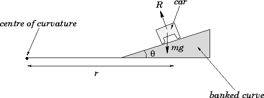
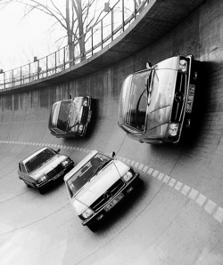
If you raise the outer rails instead, as the train is pulled around the curve is is being pulled off the curve.  A racing car on a race track there is centripetal force keeping it place. Note below  the banking for a car NOT a train.


\begin{figure*} \epsfysize =1.75in \centerline{\epsffile{bank.eps}} \end{figure*}

Mercedes cars on the Untertürkheim test track.

A car is not being pulled if it was it would be pulled off the road. Your trains cannot move fast enough to use centripetal force to stay on the tracks.

As a point of continuing education, the term used in railroading is not "banking" but "Superelevation."

In your situation, to prevent stringlining on a 3.8% grade, you would actually want to Superelevate your curve to the OUTSIDE of the curve, not the inside, as would be the case with a more "normal" curve. On your grade, you would raise the inner rail about 1/16".

Superelevation is a very subtle but effective method of making your trains look more realistic, but it has to be done carefully and in very small amounts.

@BillYo414 posted:

My question is how much can I reduce my chance of string lining by banking my curves?

Probably a negligible effect on the resistance  to string lining.  You will have much better resistance by making sure all you cars are properly weighted (preferably to NMRA standards, but at a minimum no super light cars in the middle of a bunch of heavier ones), making sure all your cars have the same rolling resistance, and maintaining a steady speed through the curves.

Incidentally, railroads bank curves (called superelevation) to provide even wear on the rails and wheels, and, in the case of passenger trains, to prevent the passengers from feeling like they are being pushed sideways.  Nothing to do with preventing derailments.

Also, the drawing above is not correct.  It is missing the centrifugal force, which should be represented by an arrow pointing the the right, in the same direction as the lower case "r."   This force is proportional to the speed of the train,  squared.  Also the force felt by the train is going downward at an angle into the rails. In other words it is in the opposite direction as shown by the "R".  The non arrow head of each arrow should originate at the same point where the existing "mg" arrow (which is gravity) originates .  At one specific speed, the combined force of gravity and the centrifugal force result in the force felt by the train going dead perpendicular to the floor of the car.  Thus achieving the goal in the second paragraph. 


Last edited by John Sethian

Super elevation of railroad curves was done primarily for passenger comfort. If the super elevation is “balanced” a passenger will ride around a curve with no tendency of tipping toward either side. Where passenger trains do not run, railroads use very little super elevation, maybe just a little to help ease the equipment into a curve. Probably less than one inch. On some railroads high/wide loads are not allowed to stop on super elevated curves due to the possibility of overturning when starting. When a rail car goes around a curve at speed, the car leans to the outside of the curve, which increases the vertical down force on the outside wheels, ensuring that the flange will not lift and allow the car to come off the track. If a freight train derails going around a curve too fast, the most likely cause is that the outside rail rolled over. 

On a model railroad super elevation is used because some people like the way it looks. But it can cause derailments.  The cars can tip to the inside because some physical forces to not scale.  Also very few, if any model railroad trucks are fully equalized. When I use to purchase rail cars one qualification test was to sit all the wheels of one truck on load cells.  Then in turn each wheel was raised 3 1/2”.  The weight shift on all four wheels could not exceed 10%.   That is a truck that will have no problem staying on the track when transitioning into a super elevated curve. 

The other issue is curves on a grade. All real railroad wheels are pressed onto the axle, so to go around a curve some of the wheels have to slip.  Do not believe the old wives tale that the small amount is taper on the tread is to compensate for this. That taper may help keep the wheels centered between the rails, but it’s origin is that it is the draft angle for when wheels were cast.  Railroads built after maybe 1880 were probably “compensated”.  This means that on a grade the increased train resistance resulting from the wheels having to slip on a curve was compensated for by reducing the grade around curves.  Each degree of curvature was equal to about 0.1% of grade. For example on a railroad with a maximum 1% grade would reduce the grade to zero on a 10 degree curve. 

For a model railroad the grade equivalent of a curve would have to be determined by experimenting, but I am sure most of us are aware that our model trains slow down when they go into a curve. When the OP talks about a curve in the middle of his grade of a half circle of 72” diameter track, this would be an ideal place to reduce the grade to reduce the train resistance.  This would reduce the increased load on the locos and reduce the possibility of pulling the cars off to the inside of the curve.

Last edited by David Johnston

The other issue is curves on a grade. All real railroad wheels are pressed onto the axle, so to go around a curve some of the wheels have to slip.  Do not believe the old wives tale that the small amount is taper on the tread is to compensate for this. 


I don’t think that it’s necessarily an “old wives’ tale” as there are current refurbishment projects that involve switching from cylindrical treads to conical ones to reduce noise and railhead wear. 

I have attached a picture and Anyrail file. I have the grade called out in three sections as A, B, and C. A 0 is the start and you can see where that section ends and B begins and so on. I'm wondering why I split it up as I'm typing this but the distances are there. It comes out to 24" over about 619.07" = 3.87%. I would rather not give up 65 square feet for a helix but I would REALLY rather not be picking up cars and breaking engines. I never really liked helixes and I would probably hide this one behind wood. I was willing to forego the realistic appearance of a 3.87% grade for the ability to have two operation levels while only sucking up minimal square feet in the basement. More on that in the second to last paragraph. 

I feel kind of dumb for not realizing that banking inward won't help unless I'm doing real world 40+MPH. It would be a heck of a train but it sounds like an outdoor project for the future. 

The train lengths would be as short as necessary. I wouldn't expect to exceed 10-12 cars. I would mostly be running boxcars and tankers up there as that stuff would be supplied to industries on the upper level. I still gotta say a helper is very appealing and I intend to use them even if it is for show. I think the DCS or Legacy lash up abilities will help me do it alone unless the locomotives have to be right by each other for that. 

I did think super elevation (as I now know it's called) would look cool and I think I may actually go for it on the A section because it's so gentle. It sounds like a horrible idea on the B section, obviously. I suspect I can lower the grade a touch on the B section and then ramp back up on the C section because the C section will disappear from sight while you're standing. It won't be visible until you sit down to run trains on the lower level. Even then, I'm considering putting a backdrop in front of it. Otherwise the train will be in the sky. I love the shot at making a totally amusing origin story for how that happens but I feel like I'm going to hate it if I can see it. 

Thanks for the all the explanation guys! I'm glad I didn't get smacked around for a question that I feel like I should have known the answer to. A curve super elevated outward is funny to imagine although I guess it would work. I think I would have a heart attack watching the train go through every time though.

NIWShelf3Bottom-RCS

Attachments

Images (1)
  • NIWShelf3Bottom-RCS
Files (1)
Last edited by Rich Melvin
@BillYo414 posted:

I feel kind of dumb for not realizing that banking inward won't help unless I'm doing real world 40+MPH. It would be a heck of a train but it sounds like an outdoor project for the future. 

It's not as bad as it sounds.  Given the curve radius of our smaller trains, a scale 40MPH would probably work fine.  However, even in the prototype, a train long enough for the string-lining case to be of concern wouldn't be doing anywhere near 40MPH up a 3.8% grade.

I think the DCS or Legacy lash up abilities will help me do it alone unless the locomotives have to be right by each other for that. 

They don't, however if you rely on the cruise control in the locos, I think the results could be potentially catastrophic.  If the rear engine is moving a tad faster than the front, you will squish the train.  If it's slower, it will make the tendency to string-line worse.

In any case, I think the rear engine would need to be manually controlled and coupler slack closely observed.

@rplst8 posted:

...

They don't, however if you rely on the cruise control in the locos, I think the results could be potentially catastrophic.  If the rear engine is moving a tad faster than the front, you will squish the train.  If it's slower, it will make the tendency to string-line worse.

In any case, I think the rear engine would need to be manually controlled and coupler slack closely observed.

I was under the impression that speeds were matched when you're in lash up mode. At any rate, I suppose I could get two of the same locomotives. But we'll see. I still have to paint the walls, carpet, and build the table. Meanwhile the holidays are coming up. I probably have plenty of time to think about this. 

The only other thing I thought about on the way to work is a single track elevator behind a back drop where section C is. I need to get the top and bottom track plans open at the same time but that might work. I could put it behind a mountain and backdrop in a tunnel. It would be invisible and a maintenance nightmare.

I lashup/MU my locomotives, both Legacy and PS-3 in DCC mode.  They are very well speed matched, and I have not had any issues with squishing or pulling apart trains with helper locomotives mid or rear train.  But my layout is flat(ish).

Also, for the fun of it, I did superelevate my curves, which are O72 and O54.  As I used Atlas track I have Midwest cork roadbed under the track.  For the superelevation I got N scale cork and just lined it up to the outside gluing it to the top of the O cork.  It adds a subtle tip and looks nice.  I haven't had issues with string lining or tracking of trains.

@BillYo414 posted:

I was under the impression that speeds were matched when you're in lash up mode. 

For the most part this is true.  However, speed matching is not perfect and even if the error is say, 0.01%, after several trips around the layout, there will be stretching or compression of the consist in between.

The only other thing I thought about on the way to work is a single track elevator behind a back drop where section C is. I need to get the top and bottom track plans open at the same time but that might work. I could put it behind a mountain and backdrop in a tunnel. It would be invisible and a maintenance nightmare.

I'm in the process of re-wickering my multi-tiered layout design to avoid some of those pitfalls.  It's fun stuff.  Thank heavens for the layout design software.

Thanks for the tip @sinclair. I actually have all my huge curves buried under mountains but I might consider not doing that if superelevation makes trains look better going through curves. This would save me a great deal of time in mountain building. 

@rplst8 the design software has definitely made things easier and a lot cheaper. I remember countless trips to the hobby shop for different tracks when I was learning. This was especially handy when I decided to change the layout to Ross Customer Switches. 

In a model railroad it is not Super Elevation; it's reverse banking.  Sorry if my earlier post was confusing. To show the physical effect of a moving a train train cars on a curve,  not a single automobile car; take a string and attach one end to the center rail of any curve track. Pull on the loose end of the string along the track.  Note the direction of the string'a movement as it is pulled.  The string moves toward the INNER radius. Which is the direction the cars on the train will move toward as pulled by an engine.

However, if you "reverse" bank not super-elevate, the cars will tend to stay on track as the wheels are being pulled into the reverse banked track.

Now the reverse banking under the inner side of the curve is "slight" maybe the height of a Popsicle stick but it is better than elevating the outer rail.

Last edited by AlanRail

I don't have Anyrail installed, and I can't view the dimensions in the small font on your .jpg attachment.

IMO 3.9% is too steep to look real.  For example, if the graded section contains a bridge, one side would be noticeably higher than the other. 

Given the length of your room, I wouldn't hesitate to put a full-width helix on the bottom (left) end.  You'll never miss that 7 or 8 feet.  But it will almost double your layout surface area, mainline length, and increase operating reliability.  The grade inside the helix would be a steady 2.8% or less, which is more manageable than what you have right now.

I know you're tempted to vary the grade in your original plan, or perhaps even have some flat sections.  However-- every time you change the steepness of the grade you have to do so with a gradual transition.  This is a must!   Unfortunately this wastes a lot of linear distance and makes the steep parts of the grade even steeper.  Once you're on the grade for the sake of operating reliability it's better to just get it over with.  Likewise with curves.  That's the beauty of the helix.  True there's a lot of drag because of the curvature and the grade.  But once your train is in there the tension on the front coupler doesn't change until you reach the top.  I'm pretty certain that a 10-12 car train won't be a problem in a 2.8% O72 helix if all cars are weighted similarly.  A rubber-tired loco should be able to handle it without a helper.

So my advice is to build two full-length, level decks with the helix connecting them.  Helixes aren't prototypical, so I agree- hide it behind Masonite panels.  You can hold the panels on with magnets so it's easy to remove them and get your hands in there when you need to.  The focus would be on your two operating decks, and no one would have to know what's behind the paneling.  The train would go into a tunnel at the bottom, and then magically reappear on the upper deck.  Of course you'll need a reversing loop, run-around siding, wye, etc. on your upper level so the train can use the same helix going back down.

Trains won't be going to and from Shangri-La.  It can all be scenicked and part of the operation.  Depending on your height and whether you want the layout to be child-friendly, you could set your deck heights at 36" and 60" or something like that.  Plenty of separation for a valance with LED lighting, and tall scenery on the bottom level.  Most folks make the bottom level wider than the top, but it depends on your height, whether or not you plan to use a shadow box-type valance, and of course your track plan.

Now you just have to decide what you're going to do with the extra 160+ sq ft of surface area this approach gives you!

Last edited by Ted S
@AlanRail posted:

... is "slight" maybe the height of a Popsicle stick but it is better than elevating the outer rail.

I was picturing almost a quarter inch. I have to wonder if an untrained eye would even really notice. 

@Richie C. are you saying to cut cardboard as a guide so things can't fall too far off the track?

@Ted S I didn't realize how small those dimensions are. I'm looking at about 40' of length. Technically, I probably have the space to comfortably achieve 24" of lift in a straight line but you guys have just about talked me out of it. It's one of those situations where the novelty will probably wear off after the third derailment. Especially because I'll be stretching to retrieve cars in the middle of a 72" circle. I was eyeing the possibility of a roundhouse in the area where the helix would go. With that said, I've been tinkering on Anyrail most of the evening and I think I have space to run a 10 foot stretch of track straight up. I'll be working in a 5" wide area to do that so now I just have to look at my options for fitting something inside of 5". I like the elevator idea because I can still keep many square feet for anything. The time taken to get over the helix is definitely an advantage in my eyes and the helix is the fall back plan. I think it's the safest bet and will work no matter what. I'm going to see what kind of illusion I can work with in a back drop for the helix to try to reclaim that space. 

Is Anyrail a popular track design program or no? I would like to get something that is popular so people can see what I'm working on. I like the program because I find it mostly simple and easy to use. 

I think AnyRail is in the top 3 in terms of popularity, with RR-Track and SCARM vying for first place IMO.  They're all good but a few years ago when I got heavily into layout planning, I thought that SCARM had better overall 3D capability than RR-Track (although the mountains look like wedding cakes!)  The ability to playtest in 3D with up to three trains moving at once sold me on SCARM.  I think you can playtest your AnyRail designs using a software called TrainPlayer.  But that's strictly a top-down 2D simulation.  I've recently seen some AnyRail layouts rendered in 3D and they looked good.  I never got around to installing it but it's on my to-do list so I can view layout designs shared on the Forum.

I'm not sure what you mean by an elevator.  Do you mean that a lengthy section of straight track moves vertically?  Would you change the height with pulleys, a motor, or ??

A helix could go at either end.  You don't have to sacrifice your roundhouse, just chop a few parallel straights out of the middle.  I'm assuming you would use O72 or O80 sectional curves for the helix.  I would make it constant-radius as wide as the end blobs of your existing design.  Allow about 6 1/2" to 7" between successive levels.  There would be room to duck under and get inside of it if absolutely necessary.  You could hide the front with a display shelf that swings out on door hinges.  If that shelf will be holding locomotives, it should be supported by its own swivel casters.  Or, you could build a dummy wall all the way to the ceiling, as long as you can get up inside the helix by going under the main board.

Do yourself a favor- calculate your platform area and mainline length with each of these options.  Even if you don't include the track of the helix itself, I'll bet that you end up with a layout that's 70% larger with a helix and two level decks.

I haven't looked into the other stuff that Anyrail can do but you got me interested. I wouldn't mind learning SCARM and RR-Track so I also could check out plans on the forum. I guess I mostly use the software for figuring out what pieces of track I need to get things to line up. Plus I can plan for routes and switching moves. 

There are two section of block that stick out from my basement wall (the white spots on the left side of my low resolution picture that I need to fix). I can fit a 10' long section of straight track in there and still have room to get a locomotive in and out. From there, my fastest design idea is a 2x4 with linear bearings running on the linear rails and a lift screw at each end connecting by a chain to keep it going up straight. A pulley system off a single axle would also work. I could fit this behind a back drop that I was going to put up anyway. I will just need to move the backdrop forward an extra inch or so. Then there are mountains at both ends of the layout so nobody would ever see the train getting to different levels. Maintenance will suck though. I need to solve than and I need to figure out what to do if for any reason the train gets stuck back there. But we'll see. 

I figured the same. 072 or 080 for the helix. I was thinking I could switch to tubular track if I went with 072 and save some money. Especially if it's going to go around many times. I haven't ran numbers on that helix just yet to figure out how long it would be. I like the idea of using magnets to hold the masonite up though. That's super easy. I think the helix is fail proof. It will work no matter what and there are examples out there. The biggest benefits I see are conveying distance by having the train disappear for a while and having no limit to the length of train I can run (within reason obviously). Plus I technically still have the option for a helper locomotive if I want to for fun. It would be purely for show, obviously. But I'm good with that. I also found out while messing around last night that getting rid of the long grade that ran in the middle of the layout would gain me a lot of space for round house/engine stall and they would make sense because they're at the end of the yard instead in a hollow created by a grade. 

I should probably run the numbers on this layout. I might need a home equity line of credit to afford the track haha

Yes- you want to use the widest curves possible, but I wouldn't have the helix protrude beyond the depth of your benchwork as you've drawn it.  A circular helix will have a square footprint and probably take up the smallest floor area.  I don't see much reason to go wider than O80 because at 7" between levels you're at a 2.7% grade which is manageable with 12-car trains.  Remember, as the helix grows, it reduces the width of BOTH level decks!

I would NOT mix O72 and O96 curves.  That's false economy.  Remember what I said about the coupler tension.  Once you're in the helix you want it to be constant.  Not oscillating as the drag and geometry changes through varying radii of curves.  My $.02.

I appreciate the comments, for sure. I think hiding the 72" diameter (plus some for overhang) helix in a box can be explained away by a mountain. Plus I can still make use of said mountain. It's becoming more appealing by the day just for the ease it would give me. It might be enough to get me up and running. There's really not much that has to change track wise for the helix either. The top level entrance/exit would still be behind the coke plant against the wall and the entrance/exit on the lower level would still be in a mountain. The difference is that the mountain is two feet tall. No big deal considering I already intended to have one there. 

Add Reply

Post
The Track Planning and Layout Design Forum is sponsored by

AN OGR FORUM CHARTER SPONSOR
×
×
×
×
Link copied to your clipboard.
×
×