My approach to closing the gap between MTH Alco PA's


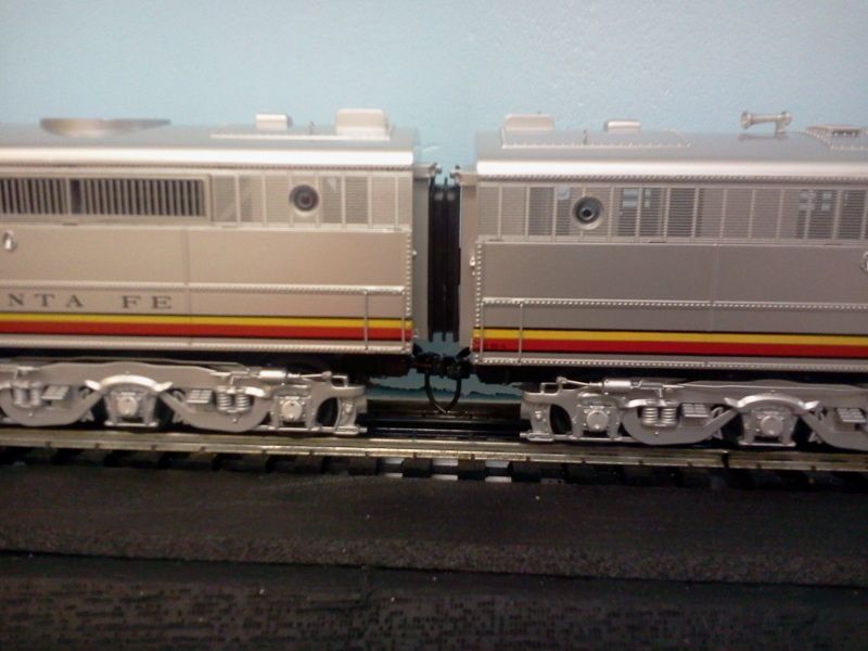
BEFORE:  The space between the units is 1.63 inches.  Scales out to just over 6.5 FEET.  
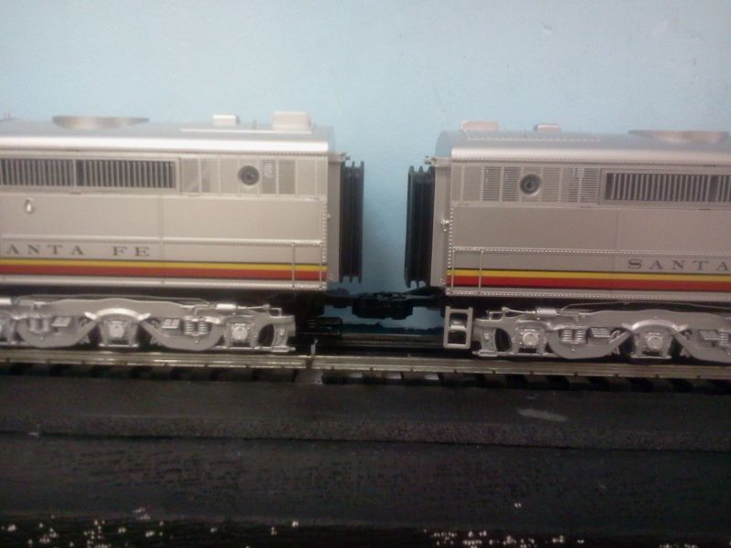


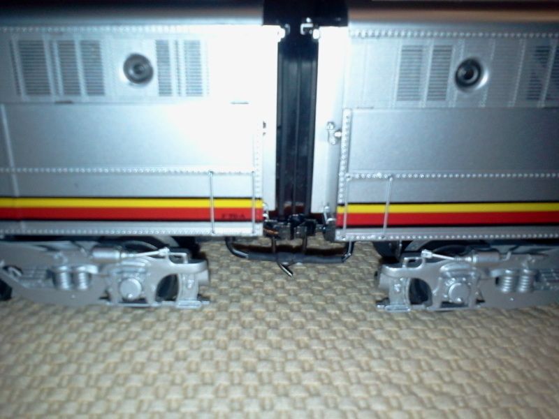
AFTER:  The spece between the units in now .65 inches.  This scales out to 2.6 FEET.


Earlier in the year I purchased the Premier Proto-3 version A-B-B-A set of MTH Santa Fe Alco PA's.  I was a little disappointed that there was so little improvement on the exterior over the same Proto-1 set that I purchased 20 years ago.  As far as I could tell (since I sold my original set many years ago and a side-by-side comparison impossible) the lift rings on top was the only outwardly visible change.  The internal changes: Proto-3 and the trailing "A" is now powered and has smoke.  In the Proto-1 version the trailing "A" only had a light package.


The inner-most axle on all units still have the plastic blind wheel sets.  The rear ladders for all the units are still attached to the trucks and not the body.  The thick black cord that runs from the rear of the lead A-unit to the rear of the trailing A-unit is still under the dummy couplers and very difficult to connect.  In addition, this cord is just plain ugly.  Only the lead "A" has a speaker which is VERY obvious when an A-B-B-A lash-up is passing by.  All the engine sounds in the first unit followed by total silence from the last three.


Soooooo, I decided to buy a digital caliper, a wheel puller, an additional speaker, some scale wheel-sets, 3 pair of Kadee #805 couplers, some min-tronics 2-conductor wire sets (for the additional speaker) and some cutting wheels for my Dremel.   Then I got to work.  


My tasks are detailed below in the order performed.


1 - Drop all the trucks, remove the side frames and cut off the the ladders.


2 - Remove the blind wheel sets and replace them with N/W Shoreline scale wheels.


3 - Remove the dummy couplers and cut off the excess metal (about 1/2") so that my home made mounting pads for the Kadee couples could be attached on the underside of the frames.  Mount the couplers.


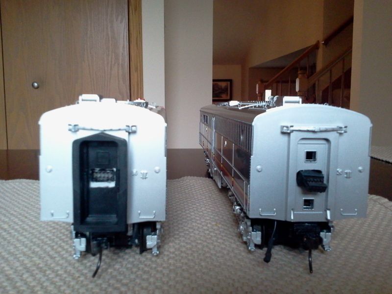
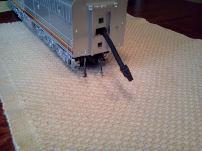
4. - Re-route thick black cable through the rear doors.  The male side was super-glued to a cut-out in the door.  The female counter part was passed through the opposite door and is free and easy to connect to the male.  After the connection is made and the units are coupled together the cable is completely hidden.


In the picture below the left side is male connection re-routed through the door of the lead "A".  The right shows the "B" which has the retractable female connection.


This picture shows the "B" with the cord fully extended which allows for easy connection when both units are on the tracks.  Ten times easier than using the MTH method of connecting the cables under the lobster claw dummy couplers.


5. Drop the fuel tank on the lead "A" and solder feeder wires to the speaker post which will drive the 2nd speaker in the second B-unit.  The result will be a more even distribution of the diesel sounds.  The speaker in the "B" is mounted to face up and directs the sound to the large exhaust fan on the roof.  Since the lead speaker faces down, having the trailing speaker face up alters the just enough to give the "audio illusion" of additional diesels running.


The speaker wire is connected in parallel from the lead "A" to the second "B".  This is accomplished by the 2-conductor wire mentioned earlier.  I chose to run these wires outside the doors to give the appearance of actual connections between the units.  The wire is visible in all the previous pictures but the picture below shows it connected.  It can be adjusted higher or lower.  I may decide later to run this connection through the doors as well.  But, for now I like how it looks on the outside.


The only remaining task is mounting the ladders.  I could use the ones that I cut from the side frames in step #1 but I am first going to see if I can get different ones 3-D printed for a reasonable price.


Note: I am only using rubber a single diaphragm between the diesel lash-ups.  This works out fine because one is all the space would allow and when coupled together the diaphragm neatly fits inside the opposite door frame.


The next big test will be when I run this on the club layout in a few weeks.

Last edited by SantaFeJim
Original Post

Replies sorted oldest to newest

Like the look. The only caution I would give is against parallel connecting the speakers as it cuts the impedance in half. That may not be good for the amplifier. In the case of a locomotive equipped with a single 4-Ohm speaker, I'd put two 8-Ohm speakers in parallel (+ to +/- to -) to provide the proper 4-Ohm impedance. I have an FT set I'm looking at re-working for close coupling and drawbar connection on the A/B pairs. 

Originally Posted by SantaFeJim:

Thanks for the tip Matt.  How about a resister before the 2nd speaker?  

Doesn't quite work. The math formula is kinda cumbersome.


Impedance = 1/(1/R1 + 1/R2 +...+1/Rn). So in the case here, the impedance would be 1/(1/4 + 1/4) = 1/(1/2) = 2 Ohms. Adding a resistor to the second speaker could actually reduce the impedance unless you put that same resistor on BOTH speakers. Also be concerned about having resistors of sufficient wattage.


What I've been shopping for is good 8-Ohm speakers so I can put two in parallel for 4-Ohm loads (3-volt Proto-2) and two in series for 16-Ohm load requirements (5-volt Proto-2). Haven't found ones I like yet.

Last edited by AGHRMatt

For my money, the MTH PA body is as good as it gets, so long as you like plastic models. I have converted three to metal (one A in nickel silver), and am pleased.  I use CLW trucks and gearboxes.


My compliments on that spacing - you need to show that to a few 2-railers.  I am seeing videos posted on the 2- rail forum with passenger cars spaced like your original photo.  They tell me it is an optical illusion, but it sure looks like a six foot jump for the miniature passengers to me!


Originally Posted by AGHRMatt:

Like the look. The only caution I would give is against parallel connecting the speakers as it cuts the impedance in half. That may not be good for the amplifier. In the case of a locomotive equipped with a single 4-Ohm speaker, I'd put two 8-Ohm speakers in parallel (+ to +/- to -) to provide the proper 4-Ohm impedance. I have an FT set I'm looking at re-working for close coupling and drawbar connection on the A/B pairs. 


Matt, I need to make sure I understand you explaination before I proceed.  Are you saying that if the factory unit contains a 4-Ohm speaker and the speaker that I placed in the dummy B-unit is 8-Ohms, that I should go back and replace the factory installed 4-Ohm speaker with an 8-Ohm speaker?


Question #2.  If the factory installed speaker in the lead unit is 8-Ohms I leave it in place can I then install 2 more 8-Ohm speakers (in series with each other) in the dummy B?


The last thing I want to do is damage the amplifier.


Thanks in advance,


Originally Posted by SantaFeJim:
...

Matt, I need to make sure I understand you explaination before I proceed.  Are you saying that if the factory unit contains a 4-Ohm speaker and the speaker that I placed in the dummy B-unit is 8-Ohms, that I should go back and replace the factory installed 4-Ohm speaker with an 8-Ohm speaker?


That is correct, based on the + to +/- to - connection you're making.


Question #2.  If the factory installed speaker in the lead unit is 8-Ohms I leave it in place can I then install 2 more 8-Ohm speakers (in series with each other) in the dummy B?


No. What you always want to end up with when adding additional speakers to the mix is the same impedance (resistance) you started out with. If the lead unit speaker is 8-Ohms and you wanted to add two speakers to the B-unit it would get messy, but it is doable. You'd have to put a 16-Ohm single speaker in the lead unit, put a pair of 8-Ohm speakers connected in series in the B-unit, then parallel that set to the speaker in the lead unit. That would give you 8 Ohms impedance for the whole system. It gets tricky because you have to manipulate the combinations. I'll put together a drawing and post it. 


The last thing I want to do is damage the amplifier.


Thanks in advance,


Last edited by AGHRMatt

OK Jim. Here you go. The three diagrams would keep your sound amp from seeing too little resistance. Keeping in mind that the standard for Proto-2 is 4-Ohms, you need that as a minimum.


If you get an Ohm meter and tinker with the combinations, you'll see how the resistance changes.


The first example replaces the single 4-Ohm speaker in the lead unit with an 8-Ohm speaker in the lead unit in parallel with an 8-Ohm speaker in the B-unit. The net impedance is 4 Ohms.


8-ohm Parallel


This next one puts two 8-Ohm speakers in parallel inside the B-unit and retains the 4-Ohm speaker in the Lead unit. To keep at or above the 4-Ohm minimum, the 4-Ohm speaker is wired in series with the 8-Ohm pair for a net impedance of 8 Ohms.


 4-ohm series-connected to 2-speaker B-unit


This is one I was looking at for my ABBA F unit sets. It puts each AB pair in series, then connects the two AB sets in parallel for a net of 4 Ohms. The beauty of this configuration is that if you just ran the lead AB pair, the amp would see 8 Ohms and not suffer from insufficient impedance.


4-Ohm series-parallel A-B-B-A Configuration


Attachments

Images (3)
  • 4-Ohm series-parallel A-B-B-A Configuration
  • 8-ohm Parallel
  • 4-ohm series-connected to 2-speaker B-unit
Last edited by AGHRMatt

Matt -


This is GREAT.  Next week I will open up the units, get out my meter check the Ohms on the currently installed speakers and figure out a combination that will work for me.  


These drawings make is very easy to understand.  I am sure that there are more than a few Forum members that will benefit from your drawings.  You already have got me thinking about now adding sound to the other B-unit as well.  


Your motto sure sums it up:  "The best service you can provide for the hobby is to pass on what you have learned." 


Thanks-a-million.  


Jim


No problem. My dad's hobby was HiFi and he showed me some literature of a speaker called the "Sweet 16" which had 16 speakers of various sizes within the enclosure. They were wired in combinations of series/parallel connections to yield an 8-Ohm impedance at the connection for the amp. The purpose was to take advantage of the sound characteristics of each speaker to provide clean full-range sound and strong bass. He was interested in building one of his own from scratch. Never built it but seemed to have a lot of fun designing it...much like me and layouts.

Santa fe Jim,


Great article. I just bought a legacy ABA Santa Fe Alco PA set from a member and that is exactly what I want to do regarding the lash up. For sound in the dummys I'm wondering if the ERR mini commanders driving separate railsounds would work ?


Are you going to fix the pilots? I've got to find some plan drawings to see if adding a pilot spacer would yield a prototypical pilot depth or be too long.


Thanks for sharing.

Last edited by Ron H
Originally Posted by Ron H:

Santa fe Jim,


Great article. I just bought a legacy ABA Santa Fe Alco PA set from a member and that is exactly what I want to do regarding the lash up. For sound in the dummys I'm wondering if the ERR mini commanders driving separate railsounds would work ?


Are you going to fix the pilots? I've got to find some plan drawings to see if adding a pilot spacer would yield a prototypical pilot depth or be too long.


Thanks for sharing.

Would really sound cool with sound eminating from all the units.


Not sure the MTH Alco's have the same pilot issues the Lionel ones do.
(Though they do have that funky cord which must thread from A to A unit through the B units...)

Originally Posted by c.sam:

How do the Lionel and these new MTH PAs compare for level of detail and fidelity to prototype?

According to Bob Turner (bob2 here on the forum), the MTH PA model has the most correct nose & cab. Since Bob is a well nown O Scale scratch builder, I thus assume he measures every single dimension & detail, in order to make such a statement of opinion.

Add Reply

Post
×
×
×
×
Link copied to your clipboard.
×
×