guys, I have a question for those who my know. In the future I am planning to have a main control pannel with my legacy remote cradles and my two zw-c's mounted in the middle of them. I was thinking of adding digital volt meters for my zw-c channles reset into the panel just below the zw-c's. being electronically challenged I need some advice. while searching ebay I found these meters that are the look I am going for. I took screen shots of them and the specks gor them. my question is will they work for my intended purpose?
Replies sorted oldest to newest
The ZW outputs AC only. You're going to have a tough time measuring AC current with a DC meter unless you wire them in parallel and build a bridge rectifier to flatten out those waves.
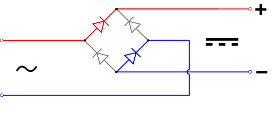
http://avidic.ir/public/show-w...688/Bridge-rectifier

oh snap! thanks I forgot about the ac current. guess I will keep searching.
Lionelzwl2012 posted:oh snap! thanks I forgot about the ac current. guess I will keep searching.
it's simple enough to build a diode bridge like listed above out of singular diodes... or you can get ready-made solutions from places like digikey:
https://www.digikey.com/produc...5-E4-51GI-ND/1217829
Here, all you would have to do is take your ac supply, splice in a little jumper and then run that up to the wavy part, then stick your dc into the flat dotted part and it should work...
Specs reveal these are DC meters, but your ZW-Cs put out AC to your track, so they are not compatible. You need AC meters.
You could add circuitry between the ZW-C output and a DC meter like the ones you show. Need full wave rectifier, 100 uf filter cap, and a potentiometer. Full wave rectifier creates DC, filter cap for a more stable reading, then the filtered DC is applied across the potentiometer, with the tap to ground feeding the DC Meter. The potentiometer is used to calibrate, because a full rectification of 18VAC will generate about 25.2VDC - so you can see there is a mismatch. The potentiometer takes the 25.2VDC across it, then you adjust where the potentiometer tap is, which you feed to the DC meter to match the DC meter's reading to an AC meter you place across the ZW-C output.
If you don't already have one, a cheap multimeter that has an AC voltage setting is available at places like Home Depot.
Full wave rectifier should be rated for 50VAC or higher, but it will carry next to no current.
100uf 50V cap should be sufficient
500K ohm pot (suggest 10 turn pot). Accuracy rating not important as you are using as a cheap calibration method.
Sorry for the crudeness of the schematic below.
Would have to do this for each meter/ZW-C combo you want to monitor.
Attachments
I run these Analog Meters on my G scale outdoor DC layout, they should work for AC also. Pulsed power does not seem to affect them. I like these because they are zero center and read in forward and reverse.
https://www.ebay.com/itm/DC-An...443?oid=122789402259
https://www.ebay.com/itm/DC-An...366?oid=122789261884
Most of the track powered digital meters have a 5v threshold and won't read below that. They also won't read in reverse.
Chris Sheldon
Just so you know, simply putting a rectifier in front of the meters won't yield accurate measurements. Not only is the voltage wrong, but the response curve will also be wrong. The only real way to accurately measure a chopped waveform is with a true-RMS meter.
The ZW-C puts out a chopped waveform which will throw any measurements way off, at the "so-called" low voltages, it's already at a peak and you'll measure max voltage, it'll change very little as the throttle is advanced. The capacitor on your filter charges to the peak voltage, referring the the waveforms below you can see that even at very low voltage settings, the peak is fairly high.


