I was thinking about installing accessory busses around the layout and wondered if others might have thoughts on this issue. My question is:

Does it make more sense to install a buss for a certain voltage to serve only those accessories, say 15 volts AC or run a 20 VAC buss to all accessory locations and do step downs?

In the first case, I might end up with 2-4 busses of separate voltages. For example, I already have a dedicated 15V buss to run all my Z-Stuff switch machines and signals.

Which of these approaches is the more elegant? Maintainable?

I do realize that the answer may depend upon the number and current draw of the accessories, but I thought we might get some good food for thought out of the discussion.

George
Original Post

Replies sorted oldest to newest

George,

I can offer an opinion if you don't mind reading one from a person that only has a Christmas layout.

I use a separate PW 'V' type transformer and one of those smallish Red transformers that used to come with Lionel starter sets to power all of the accessories on my layout. I would guess there's close to 40 lights and other types of things too. One example would be the whistle shed.

I power all of my switches from the fixed output on my MRC dual 270.

Between the 2 accessory transformers I have 5 possible voltage settings and I use them all.

I know from experience how to group sets of accessories together to share one of the 5 available settings. What I do is run a '+' wire (14 gauge) to a terminal strip connected to one of the 5 outputs. I then fan out from there to each accessory that I want to share that voltage setting. I repeat that for each of the 5 different voltage settings. I suppose you could compare this to 5 buss wires.

I run another 14 gauge wire from the '-' to a terminal strip and fan out from there to all of the accessories. I run a separate one though from the red transformer since it's physically separated from the 'V'.

I really like being able to control things this way. One thing that I found out is that many, many accessories operate well at close to same voltage. I could probably make bigger groupings and reduce the number of settings to 2 or 3, but, even though they would work together, the subtle difference provided by using different voltages makes it worth having all 5 settings available.

Wonder what I might do if I was planning a permanent layout such as you are? HMMM?

- walt
Walt & Clem:

Thank you for some interesting insights. It seems to me that we have two very different circuits in our discussion.

One type of circuit feeds intermittent use - like an accessory you activate with a push button (and then it stops) or a series of 22 switch motors (only 1 or 2 of which will be active at the same time). For this type of circuit, grouping makes sense. And Walt's buss arrangement is the example.

The other type of circuit has a constant draw - such as lights. There we have to think about loading. I need to calculate the voltage requirements of each light, sum them, and connect the appropriate voltage tap to the string (buss) of buildings / lights.

I know, this is all fundamental stuff, but it's the first time I've really given a lot of thought to it. I am planning to put a few buildings together with lights and I want to anticipate the load properly. I don't want to run more busses than I need. The terminal strip idea looks very useful there.

Other ideas?

George
One thing you want to consider is voltage spikes. If you run the old type PW solenoid type accessories such as the gate man or semaphore or Oil rig these can generate considerable voltage spikes when activated. If these are on the same line with accessories such as scale crossing gates with PC boards and LEDs the spikes generated can damage these accessories and cause premature failure. So if doing this eliminate the spikes at the source with an appropriate TVS or RC circuit or a diode on DC feeds or use a separate feed circuit for such accessories.

Dale H
Hi George

I am BUS crazy and I have a lot of multiples of the same accessory around the layout so wiring this aspect was and continues to be a major effort for me.

I run separate bus wires for each component of the layout - the turnouts, signals, accessories, lights, relays, OTC tracks and IR devices. I also use a Control Panel. There are a lot of toggles for on/off control for a lot of lite items to save bulb life and help to de-bug when things go awry, and they do.

Dale H. gave me a couple of hints with his use of relays and the common bus for all of the lighting that is on the layout that made things easier - to wire in general and to the toggles for control.

I have broken down accessories as you describe - those that require a switch to operate and are on for generally a short period of time and those that are more lite oriented - like the Industrial Water tower or Bubbling water tower - I treat these, stations/shelters and oil pumps in my oil field as lites with the other lighting [flood, etc.] on the layout. Separate bus, separate power supply, toggle switches at a central control panel for on/off using relays to simplify the wiring and a common bus for the lites.

Depending on what you have in the way of accessories and how you hook them up, you will find that some work a lot more often than you think, like the water tower or the trainman shed which in my case tend to operate when the train comes by -- I use IR devices to activate them. Others like the milk car require track power and the OTC track and I do not consider these in my accessory wiring plan.

You probably also need to think if you will use the ASC/AMC/OTC/SC2 devices to control the accessories. That may effect how you wire them. Placement of the operation controls is also a factor I considered. I have them all in ONE place. While I am TMCC/Legacy, I have chosen to not use this for all of the accessories
as I am PW oriented and find the hands-on to be more fun.


Hope some of this helps
Ralph
More good points Dale & Ralph - thank you. And all of it helps.

I don't have PW accessories on the layout. At this point in time, I have the following items (and I had to think about it):

  • 2 Lionel Industrial Smokestacks (part of the Open Hearth Mill)
  • 1 Lighted billboard on the front of the Blooming Mill
  • A set of 2 floodlight towers in the Weirton Steel yard
  • 2 DZ-1010 crossing gates w/ signals (which will be activated by an insulated rail or IR)
  • A hotel building with 4 rooms activated by insulated rail
  • A number of lighted buildings (as yet undetermined)
  • Several traffic lights
  • An industrial crane to be controlled via Accessory Motor Controller (future)
  • A 15 VAC buss already powers 22 DZ-2500 switch motors, 3 DZ-1060 signals, and 2 MTH PRR signal bridges


The only items actually on the layout and functioning right now are the switch machines and signals. The smokestacks are not hooked up and everything else is in some state of planning or visioning.

Also, I have no control panel. Switches are accessible via CAB-1 or toggles on the fascia, but lights are simply going to be powered by the accessory transformers at this point in time. The thinking is that eventually I will want to dim the lights automatically to simulate a day/night cycle, but I haven't gotten that far yet.

I might end up with a number of busses myself, just to avoid moving loops between PowerChief taps and accidentally frying lights or accessories. You know, assign one tap a known set of accessories and voltage load and be done with it. Maybe try to keep that buss servicing a specific area on the layout. It looks like I'm going to need to keep careful notes on interim configurations.

I have decided that I'm going to color code my busses differently (was planning a single Black / White one).

George

OK, having established that I will have a buss:

  1. For every group of like voltage accessories, primarily lights.
  2. For intermittent accessories like switch machines and signal tripped by insulated rail or block occupancy.

For Item #1, how do I calculate how many lights (incandescent) I can put on a circuit?  I know there is a formula, but I can't find it at the moment.

Here's what I do know:

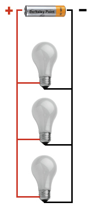
  • The circuit will be a parallel one, with a terminal strip to a particular position with feeds to the lights. 
  • I know the voltages of all the lights in the circuit.

Your suggestions are welcome.


Thanks,


George

Bear in mind that if you use a buss with multiple voltages you can share a common if you phase all the transformers together. So 4 #16 wires and 1 #12 wire will give you a buss with 4 different voltages. As long as the total output of all the transformers is less than 20 amps you're good to go. No need for 8 wires for 4 different voltages. Five will do just fine.

Ron

Now that I'm running all remote control and transformers are out of sight, I run seven different voltage taps for all voltages required.  Index cards similar to the one below are stapled near the terminal strips.  The color codes apply to the #16 and/or #18 wires.  Each voltage tap has its own circuit protection. Note the repro of the AF Drum Loader has it's own oddball tap (run a spare or two).


Postwar Z 1


A          red       sws      14-16V


B          red          16V Access


C          orange          14V

             Access – RC Tracks


D          brown          12V

             Lighting North


Postwar ZW or Z 2


A          blue          8.1V

             AF drum loader


B          black          12V

          Lighting South


C          yellow          10V


D

Originally Posted by RailfanRon:

Bear in mind that if you use a buss with multiple voltages you can share a common if you phase all the transformers together. So 4 #16 wires and 1 #12 wire will give you a buss with 4 different voltages. As long as the total output of all the transformers is less than 20 amps you're good to go. No need for 8 wires for 4 different voltages. Five will do just fine.

Ron

Ron,


I am using a PowerChief 120F accessory transformer.  It has separate tap pairs for:

  • 12 VAC
  • 15 VAC
  • 20 VAC

Plus you can connect the RED taps to make 8 VAC, 5 VAC, and 3 VAC.  The instructions note that when using these taps, the accessory or light can't be connected to any other ground. 


There is no discussion of amperage anywhere in the documentation.


George

In fact, having out of phase transformers will REDUCE the current in the Common line.  The net current is the difference between the currents flowing in one phase/polarity and the currents flowing in the other phase/polarity. 


The downside of this is that you will have larger voltage differences between the various HOT feeds.  This presents a small additional safety hazard, and it does not work if you are feeding tracks that connect with insulated pins.


If you had lots of lighting wiring that did not interconnect to any track-related control circuits, you could reverse the polarity of the lighting AC source to reduce the current in a shared Common bus.

George, we all wish there is a pat answer.  In general you note the watts available from your transformer (that should be listed on the label).  Next you start adding wattage of each light bulb.  That's where it gets tricky because low voltage bulbs don't normally have watt ratings like 120V bulbs.  Postwar bulbs use more watts than modern bulbs and LEDs used almost no watts.  If you know the volt and amp rating of a bulb, use this formula for calculation (watts = volts x amps).


Here's a wattage list from 2002 to start with.


12/20/02
Lionel postwar equipment estimated power usage:
 
Equipment     Watts
 Motor          15
 Headlight          2.5
 Car Lite          2.5
 022SwLite        2.5
 022ContrLite    2.5

From O Gauge Railroading  August/September 2007  Page 110   Jim Barrett

AC motor        40-50
DC motor        15-20
Postwar passenger car bulb      5
Bulbs per postwar car   4x5=    20
Newer bulb          2-3
Bulbs per newer car (5-9 bulbs)
Headlight bulb          2-5
Marker light bulb          2
Lionel switch bulb          5
Lionel sw controller bulb    5

If you have an ohmmeter you can figure out the approximate wattage of each bulb by using Ohm's Law. Current is equal to the voltage (you run them at) in volts divided by the resistance in ohms. Once you find out the current then multiply it by the voltage to get the wattage of the bulb. Then add the number of bulbs times the wattage for the total. 

Ron

RailfanRon, You are correct but you forget that the resistance of an incandescent light changes when the filament heats up. Better way is to light the lanp and measure the current directly using the current range on the multimeter. If your meter does not have an AC current range just put a diode in the line and use DC. If you go the diode route remember to measure the voltage at the lamp. If you are concerned about the meter's capability most meters have a ten amp or better range that should handle most lamps.


Al

Post

OGR Publishing, Inc., 1310 Eastside Centre Ct, Ste 6, Mountain Home, AR 72653
800-980-OGRR (6477)
www.ogaugerr.com

×
×
×
×
Link copied to your clipboard.
×
×