Is there a preferred/accepted way to splice two wires onto a third? I'm wiring a DZ 1002 turnout push button controller for use with an AIU, but intend to retain the push button/manual function as well. I will have 3 wires from the DZ 1000 switch machine to the DZ 1002. From the DZ 1002 I'll have a second set of three wires leading to the AIU. That's 2 wires connected to each of the 3 DZ 1002 leads. Is it best to just solder the 3 wires together and use a shrink tube over the splice or doesn't it matter?
Replies sorted oldest to newest
Jim
Are you only needing to wire one switch or will you have a lot more?
The easiest and quickest way is to use the proper size wire nut. Think about it: every junction in your house wiring is held together with a wire nut. It's also the easiest to undo, should you need to.
Jim,
I use simple old snap lock connectors to splice the wiring. They are available at HD or Lowes. You can buy them in two versions. The one you need is the RED snap lock used for connecting 3 leads together. The ones in the picture are the butt splice version (yellow) used for connecting 2 wires. There are used in telecommunications good for 20 to 26 gauge wire. No need to strip the wire ends just insert the wires and crimp with small set of pliers. You can also visit my website to see how to setup a wiring plan if you are going to be installing multiple units. www.montanarailpower.com .
Attachments
Strip, twist, solder, tape.
Snap locks corrode, and wire nuts get loose. Solder is forever.
Thanks everyone. I have 17 connections to splice.
Strip, twist, solder, tape.
Snap locks corrode, and wire nuts get loose. Solder is forever.
Strip, add heat shrink tubing, twist, solder, slide heat shrink tubing over the joint, heat the tubing with a lighter. Lasts as long as you will. Tape falls off eventually.
Wire nuts, never had one corrode on come loose in my life.
Ken M
I use old CAT 5 twisted pair all over the layout for lighting and other things. So I get the 3 way phone splice connectors. They are fast and easy. I buy them at Home Depot.
Attachments
Ideal 71B wire nuts will handle most of your needs. If the wires are too small, twist long, fold the wires over, and twist again. Available at electrical supply stores, and the two Big Box stores, electrical department, usually box of 100.
These are 71B wire nuts use on DZ 1000 switches with 20 gauge wire.
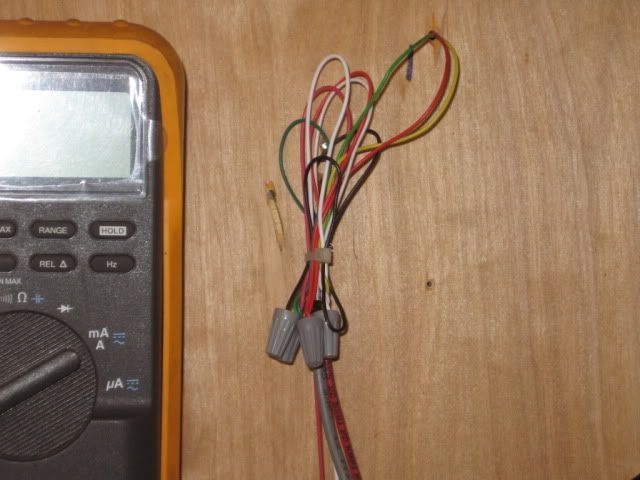
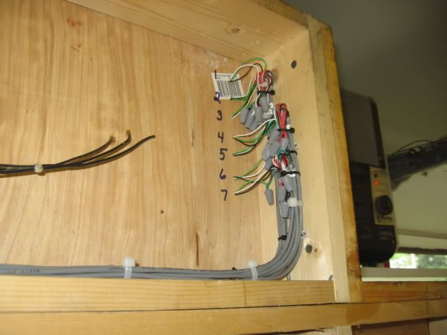
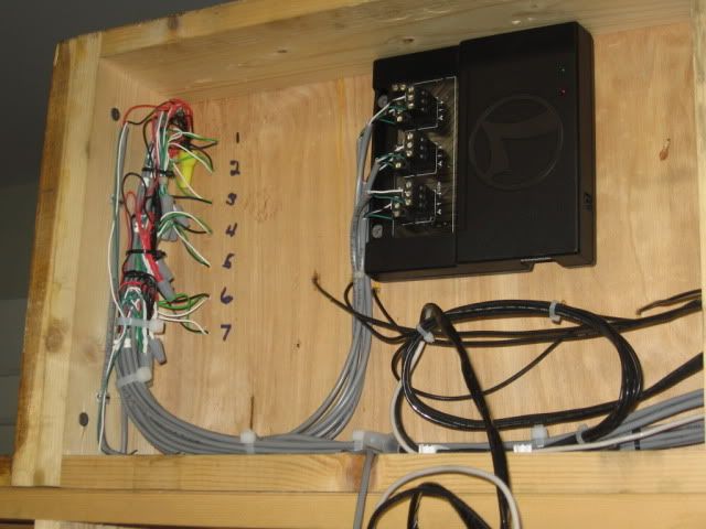
Wire nuts, never had one corrode on come loose in my life.
Ken M
We've had several instances of wire nut connections loosening inside a junction box at some of the schools I work at. This is not to detract from using wire nuts, as that is my preferred method, but it can and does happen.
Don
Jim,
You have how many switch machines to install 17 ?
If they come loose there were not put on properly or they used the wrong size.
Ken M
The phone splice connectors handle 19-26 AWG. Eliminates the need to use wire nuts. It's a very clean install.
If you want to make changes don't you have to cut the connectors off thus making your wires shorter to work with next time?
KenM
Yes that is a possibility Ken, but old CAT 5 is easily obtained. It has 4 pair. If I look back at all the LEDs I wired this way, I can think of any splices I had to cut and rework.
I'd love to see some universal plug developed for the turnouts. That would be the best solution, but then again I don't have to move stuff around after I decide where to put it. If I am making a change on my layout then the whole thing is coming down for something entirely new.
-Ted
Note the wire clamp mount Mike uses for his wire nuts. Residential use of wire nuts also calls for support at the box entrance and 8" back.
The real problem that I have encountered with wire nuts is the casual way some folks let wire nut connections hang swinging free in a wire jungle under the benchwork then proceed to crawl around stressing the connections. ![]()
The question is not so much "are wire nuts any good for layout wiring" but rather "If I go with wire nuts what is the proper way to use them".
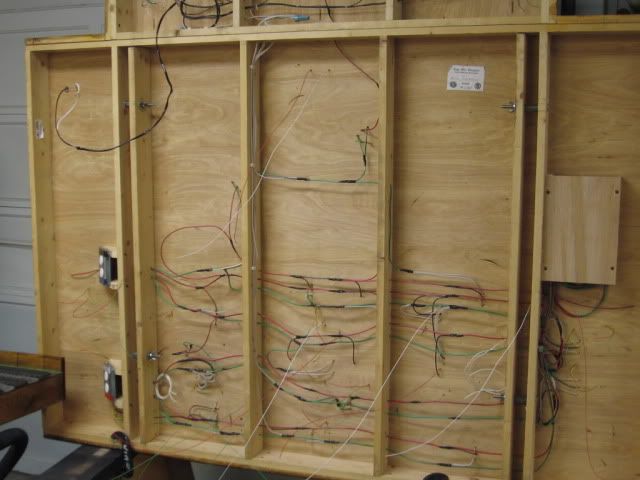
Note the ladder used to wire this layout piece.
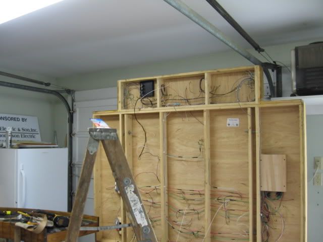

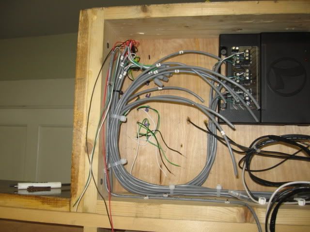
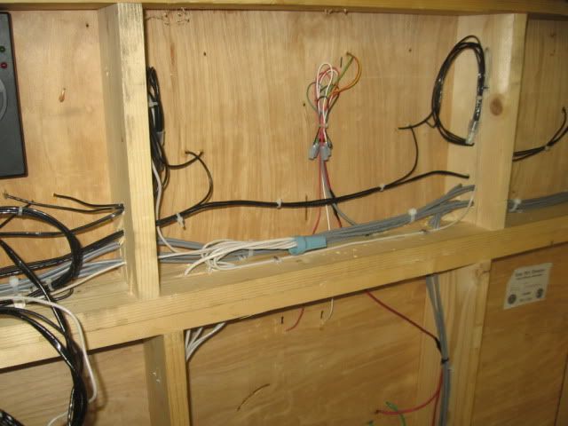
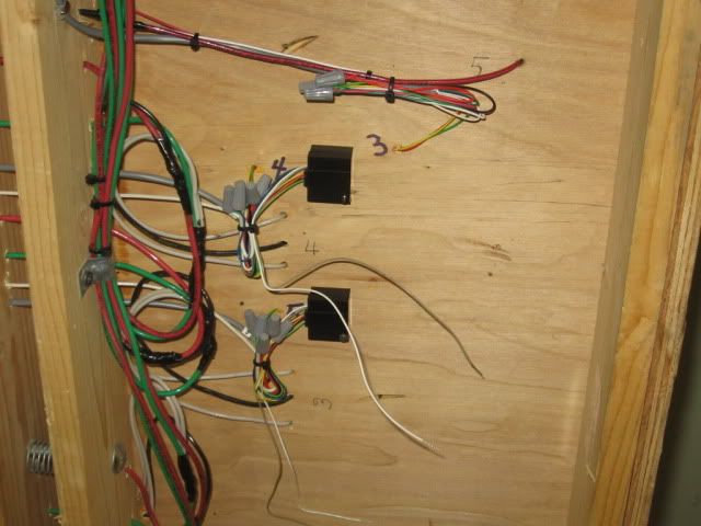
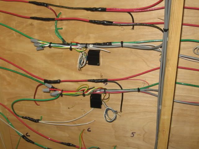
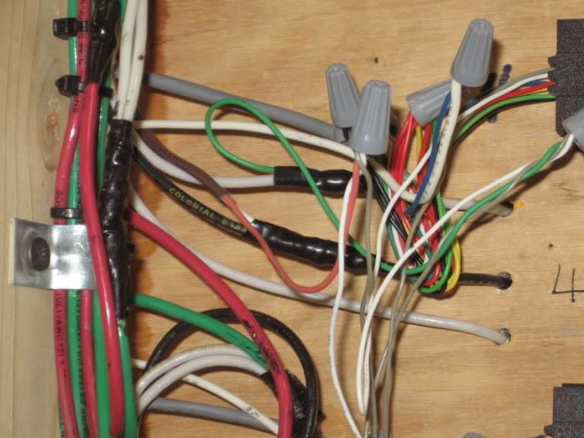
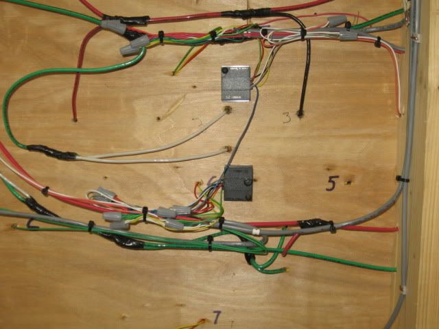
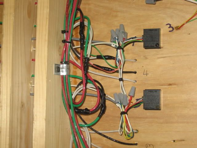
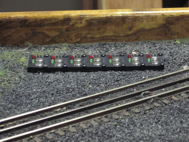
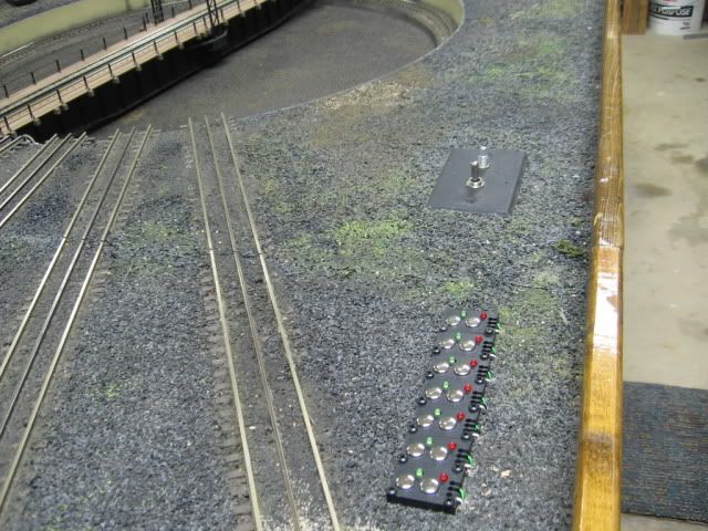
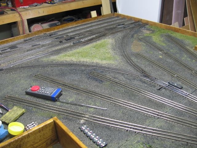 .
.
FYI------there is never ever a embarrassing question when it comes to your safety by the way.There are way too many pros on this site that will always help you.and I will attest to that in a heart beat.
Another module "Animation module" that was recently assembled. Note the metal splice box, that contains a relay and 110 volt wiring. Lower middle of picture. The relay allows, all 110 volt animation pieces, to have low voltage (18 volt) push buttons control. A safety factor. IMO.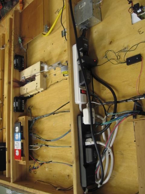
Even stereo sound on this module, who would a thunk. ![]()
Speaker upper left.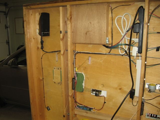
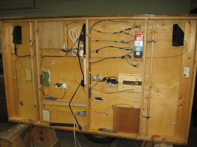
There are 6 different animated pieces, and sound, all pushbutton activated. Backhoe operation is probably the most noted piece, along with the tipping port-a-john.
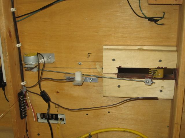
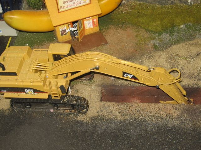
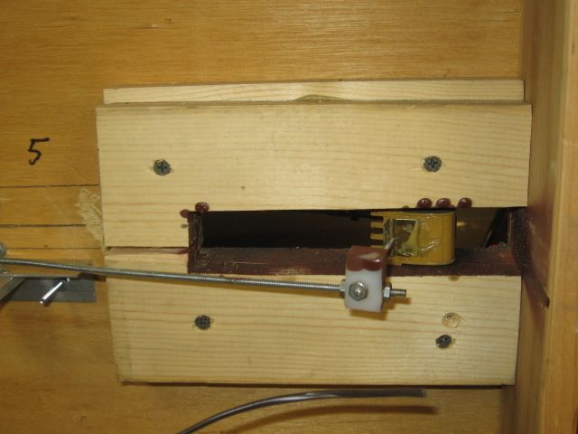
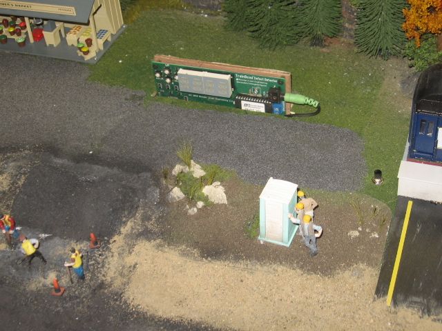 There is a box cover for this piece, used during transportation. We added a 1/4" luan board, protection piece, to the bottom wiring area, to protect the mechanical movement of the backhoe. Most of the underside of the module is exposed/subject to abuse including the speakers.
Matt Irwin's module. Matt recently had major heart surgery. ![]() Best wishes Matt, get well soon
Best wishes Matt, get well soon![]() . Mike
. Mike
Word today, Saturday,Dec 6, Matt has improved considerably, is off dialysis and is in rehab. Cigarettes are gone for ever. ![]()
Has anyone used phone jacks as connectors? I've seen them used as plug in ports on club layouts for controllers, but can they be used for other purposes, such as switch control connections?
Don
Thank you all again. I have 17 switches to wire up and I appreciate all of your suggestions. What I'm getting out of this thread are two things: there are several ways to splice multiple wires (I'll probably go with the strip/twist/solder/wrap method 'cause I already have everything I need) and wire management is crucial. Fortunately, all I've done so far is to connect the track power and I can clean that up fairly (!) easily.
Recommend the wire nuts. Just be sure to use the right size.
I built a Carvin electric guitar from their kit and used a wire nut on the output jack in case I had to open it up again. It has not been abused, but twelve years playing out in a rock/variety band is not an easy life for a guitar and I've never had a lick of trouble.
Pete
I've found enough wire nuts rattling around in locomotives that I'm not a big fan of using wire nuts if you don't have to.
I've found enough wire nuts rattling around in locomotives that I'm not a big fan of using wire nuts if you don't have to.
Fair enough, but based on my own experience I've gotta figure they were improperly installed, not tightened enough.
Pete
I agree they were probably not installed correctly, the issue is that it's easy to get them improperly installed. I like the idea of something a bit more foolproof. ![]()
I've also had wire nuts that the twist spring pulled out of the plastic jacket. The absolute best way to use a wire nut is to first, twist the wires together, second use the screwdriver with the hole in the handle made for wire nuts, to tighten the wire nut, and third, use electrical tape to secure the wire nut to the wire bundle. In instances where there is no junction box, (low voltage applications only), secure the bundle to the bottom of the layout board or framing member as shown in the photos in previous posts.
Don
This is exactly why I don't favor wire nuts for most jobs. ![]()
Here are the instructions from the Ideal 71B connector box. If there is a smaller mechanical connector available please let me know.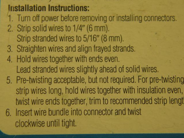

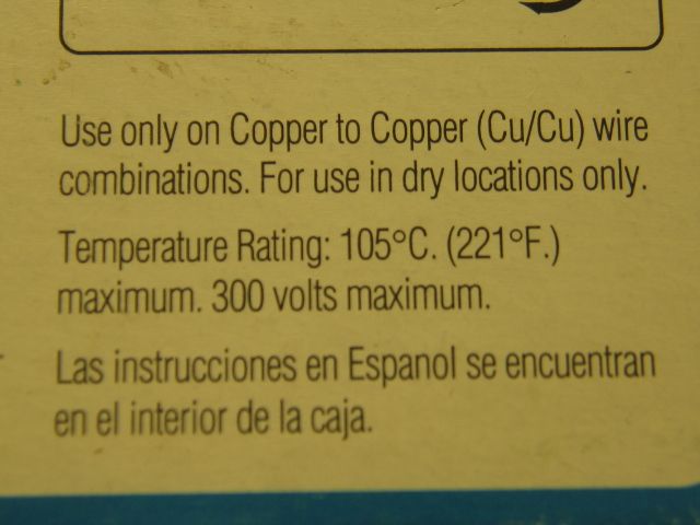
Note in the instruction picture, that the stranded is slightly longer than the solid wire. Equal length is O.K. Please read the instructions. Note that the picture shows the insulation twisted/which would indicate the splice is tight/properly done. Every different mechanical connector has instruction either on the box or bag.
For those with weak arms/hands, Buchanon supplied a plastic drive piece, in 500 bags or larger containers, for screw drill/driver application.
When you splice all day, you can easily do 300 to 400 splices. A little mechanical help is in order. I liked to use a Buchanon C24 crimp tool with Buchanon 2008 (steel) crimp rings. These connectors allowed for visual inspection to assure the wires were properly installed in the splice and in most cases, with the tool compression, was, IMO, the best/most trouble free, splice available.
Buchanon C24 crimp application.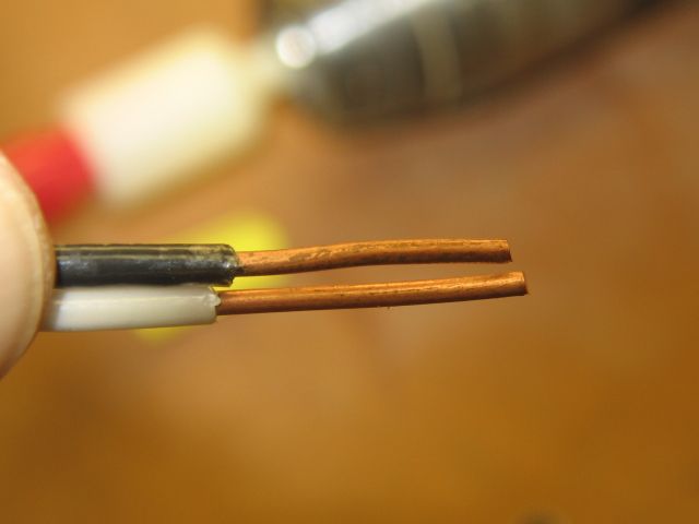
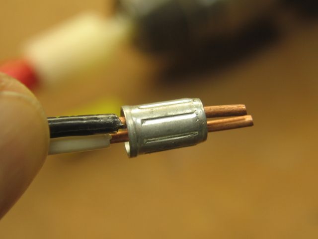
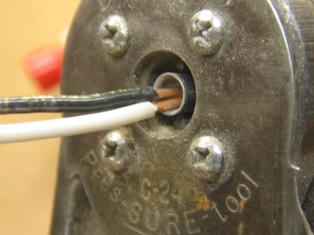
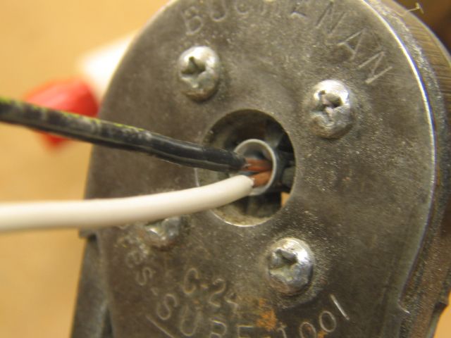
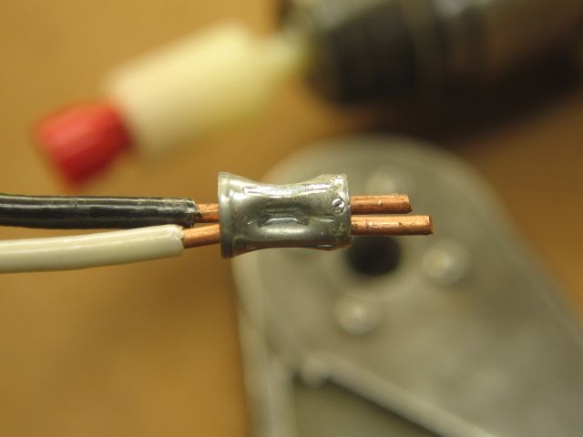
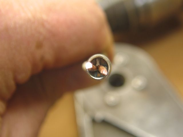
The splice is completed by clipping the excess leads, then taping with either Scotch 33+ or 88 tape. There is a push-on nylon cap, Buchanon 2007, instead of taping.
Wire nuts also make a good cap for the construction adhesive.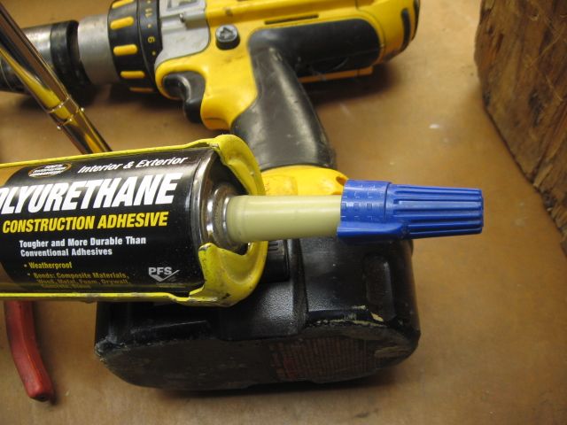
Slow Saturday evening. ![]()
Use mostly Posi Lock http://www.posi-lock.com/connectors on my layout. Easy to connect or disconnect if change is needed. Still solder if needed, however when working under the layout these connectors really simplify wire connection. You can splice three wires easily using any of there connectors. Also they eliminate the need for any shrink tubing or other wire insulation.
Use mostly Posi Lock http://www.posi-lock.com/connectors on my layout. Easy to connect or disconnect if change is needed. Still solder if needed, however when working under the layout these connectors really simplify wire connection. You can splice three wires easily using any of there connectors. Also they eliminate the need for any shrink tubing or other wire insulation.
Thanks for sharing the link those are neat.
Just some information and photos to help in your decision on wiring your Z1000 switch machines. Earlier this year I added the Z1000/2500/DZ1008 equipment to both my displays I use for Trade shows. Each display featured 3- Z1000, 3- Z2500 and 2- DZ1008 auxiliary relays and associated control buttons. I used the wire connectors described by TMack in his post. They are perfect for the gauge wire included with the switch machines and the wire used to extend the motors and control buttons to your equipment location. I used 4 conductor wire with the color code used with the switch machines. The best I have found came from Platt Electric www.Platt.com , enter item 96238. Comes in 500' rolls for $35.00 . Connecting the motors and buttons worked very well with the telecom type connectors available from HD or Lowes. For terminating the wires I use telephone 66 blocks available at most electrical supply companies or HS, Lowe's etc. I use the standoff brackets to mount the 66 blocks and route any wiring up behind the brackets (wire management). This keeps everything neat and organized . This helps a lot especially in larger installations where many switch motors and equipment are used. Although each installation is different you can customize the wiring with the 66 blocks to meet just about any need you have. For a simple straight up install you can connect 16 Z1000 switch motors and control buttons on one 66 block . Nicest part of installation came when everything worked perfectly when powered up for shot. The enclosed pdf. on wiring does not show all the wiring.The remainder can be found on my website www.montanarailpower.com
Attachments
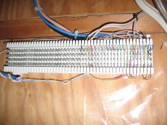
66 blocks or 110 blocks are a good choice for termination They can be purchased, either (4) terminals across, all connected, or as a split block, requiring a bridging clip between the left two punch-downs and the right two punch downs. Both 66 and 110 blocks require a punch down/cutter tool.
Ideal punch down tool with 110 cutter end.
66 cutter punch down tip. Both tips will fit the same tool.
A 66 block used for telephone distribution.
I was on a construction site yesterday installing light fixtures. We continued the twist nut conversation at lunch. I mention the Buchanon white plastic tool that was available in the large bag packages of Both the B1(yellow) and B2(red) twist nuts. The comments were that this mechanical, (be sure it's tight), application had one flaw. On occasion, using a drill/driver, you could pop the end of the twist nut exposing open wires through the twist nut end. The some what foggy head does remember that happening.


