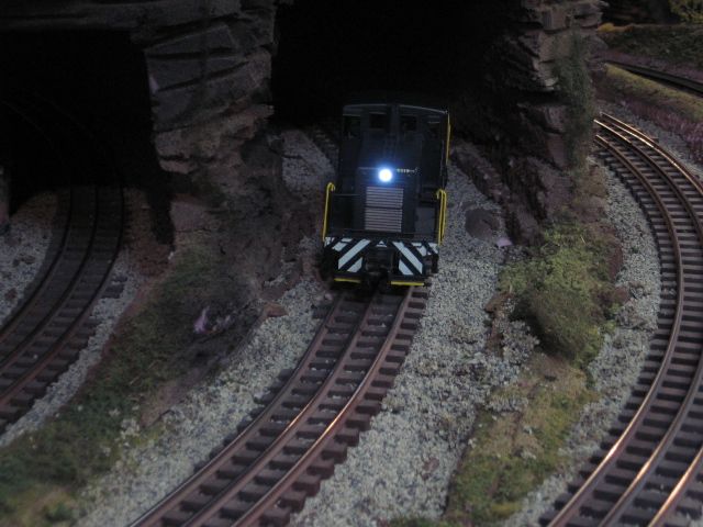
Did my first one tonight. Using a DD Motor Mite.
Bought two on the web that a forum member was selling.
Would of saved a couple of $ if I noticed sooner before he listed them but I wanted them.

Put on in a Dual motor K-line S-2 switcher.
Took about 25 minutes.

I plan on using the other one for a K-line Porter using the small tender like Gunrunner did.
Might take me a little longer. LOL. 
Anyone ever take photos of dismantling the little 0-4-0.
If John says its a PITA, I am assuming it is going to be a frustrating learning experience.

But that is a project for a different day.

My question on the Motor Mite. It is rated for 4amps.
Even though it is not recommended because the S-2 has two full size DC cans, I have not observed any signs of over heating.

For better low speed running that make two suggestions. And I did notice that they are assuming that they are miniature cans. One is series wiring, which I tried and did not really make much difference.
The other is using a diode bridge, which I understand is a bridge rectifier in line with the Dc outputs jumped.

Do these mods increase the current draw?Would not want to toast the unit.
Would I be able to use this safely to upgrade a single motor K-line 0-4-0 switcher.
I have two TMCC versions and a conventional one that I want to upgrade. I already got an extra Railsounds tender for it.
Anyone have any feedback or suggestions?

I do not anticipate this issue with the Porter. Because it seems that these are designed for small units like it.
Thanks
Original Post

Replies sorted oldest to newest

Does anyone know what the outputs are rated for.
Motor Mite says 4amps for the motor. Which could be interpreted as total.

The spec is a little vague. It says they are rated for 12.5-14v bulbs.
Does not clarify Ac or Dc. I do have the DC can version.
I would think that motor output would be close to 18v Dc.
Also does not specify what the smoke out current or voltage is.

I guess I could pull out the meter and open it back up. But I did such a good job getting everything in neatly the second time.

Thanks.

The MotorMite drives the bulbs with the Lionel R2LC that is part of the package, so it's exactly the same as other TMCC controllers that use the R2LC.  The outputs are a half-wave rectified DC under command control and AC track voltage running conventionally.  The smoke is also controlled from the R2LC, same comment applies, it's just from a higher power triac.  The standard smoke triac is rated at 2.5 amps, but without a heatsink, I'd be reluctant to pull more than 1/2 to 2/3 of an amp through it.  The motor voltage shouldn't get much above 12 volts, as that's the rating of most of the motors used in these engines.


I believe the 4A is maximum, but you'd have to have a pretty heavy load to actually draw 4 amps to the motor.  Also, I suspect things would get pretty warm if you were at 4 amps for any length of time.


Last edited by gunrunnerjohn

Most of the kits should have Lighting installation detailed.  LED usually require small voltage 1.5 volts or less.   I've popped a few.   I usually drop back to this diagram which shows resistor in series with the LED's to drop voltage. Some old information long ago shows 490 ohm resistors. in series with small (2) LED's

This diagram using two LED's in parallel show a 560 ohm resistor.  A TAS small kit, that was available at one time.

 Kind of depends on the LED and applied voltage.  I had done some ditch lights wired directly to track power at 18 volts and thought/ can't remember unless I tear the unit apart, I used 1 K resistors. 1/2 or 1/4 watt.

I was luck-ey when I hooked these head lights up on a small Rich Yoder 44 tonner to an ERR board using a 470 ohm resistor.   The LED's are bright which would indicate may be a bit more resistance is required. 

Last edited by Mike CT

Hi John,

I am still a little confused.

I have attached a scan of the Digital Dynamics wiring diagram.

I have replaced the 1k  load resister with a 470 ohm one.

I can see how this will work with VAC in conventional.

How does it work with does it work with the half wave rectified DC if the red wire is positive?


I can understand how the second one works with the back to back leds. And I assume that the bottom one would also work if I added the load resister across the outputs.


The Digital Dynamics one just seems to be odd to me.

Maybe I am missing something.

Attachments

Hi John,


Figure 8 is wrong, the polarity of the supply is incorrect.  You're right, that won't

work.


Am I correct to assume that if I switch the red and black wires it should work?


For the R2LC, the frame is positive, the lighting outputs are negative in respect to frame ground.  Obviously, the anode of the diode must face the ground connection, and the positive pin of the LED's have to face the ground connection as well.


Now I am confused again. Not sure how to visualize this.


Can you sketch it correctly for me.

Digital Dynamics says that the Red wire is positive and the Black wire is negative. Is that correct?


Thanks.

I am glad I asked the question and did not just blindly follow the diagram.


Well, I don't know where the "red wire" is connected, so I can't really say.


The circuits in your PDF work with one exception, that is the plus and minus has to be reversed on the figure 8 diagram.  The other two assume AC, so there is no polarity concerns with the LED's.


It's not a big issue, if the lights don't light, swap the pins in the headlight connector and they'll work.  It's too bad that DD didn't include one total diagram for the system, that would be useful.


you'll find that one side of the J3 through J7 headers on the motor board are all common, and they will connect to the frame ground.


An interesting point, if you use the smoke output to power an LED cab light or LED strobe, it happens to be the opposite polarity from the J3-J4 light outputs.  Just something to keep in mind.


Thanks John,
You are a wealth of information.
The Red wire is on the two pin connectors that goes to the outputs.
It makes sense now. If I use LEDs for cab lighting then diagram eight is correct.
If I use LEDs for the headlight and backup of light I need to reverse the the red and black wire.

The instructions mentions to  swap out the incandescent headlights to 14 volts if they are 1.5v connected to the original integrated circuit board.
Maybe using LEDs for headlights was not that common.

I just finished upgrading a former PS1 loco using an ERR kit.

Had problems with the LED headlamps not working.

I wound up just powering the headlamps off track power so both are on all the time. Good enough for me.

I guess I needed to add the load resistors to the light outputs which is strange because the last ERR kit I did didn't need that.

Just did my first ElectricRR TMCC conversion... well my second but I didn't take a video of the first one.  I find I hardly ever use any of the conventional locos I have.  So to make them useful I am slowly converting them.


Here is the first loco converted.  This is more of an operating session of 1990s train set rarely used since it has a convential loco.  The low speed performance is much better with the 100 speed steps.  The railsounds boxcar that comes with this set sounds pretty good considering it is 24 year old technology!


Last edited by jimmysb
I like john do like to have directional lighting and if it is built into the board why not. I have just simplified my installs by using the Evans Designs LEDs. they are a pretty nice package and come in either 3mm or 5mm, and you can have the white or the warm white. I have drilled into the headlight lenses on some of my diesels and super glued them inside the drilled hole, gives a really bright headlight and the lens looks stock.
Ray
 
Originally Posted by Flash:

I just finished upgrading a former PS1 loco using an ERR kit.

Had problems with the LED headlamps not working.

I wound up just powering the headlamps off track power so both are on all the time. Good enough for me.

I guess I needed to add the load resistors to the light outputs which is strange because the last ERR kit I did didn't need that.


The hardest one I ever did was a Copper Range 040 with the TAS docksider kit, and the hard part was getting those four wire pipes back into the pilot at the same time without scratching when putting the boiler back on. Runs well, but the original horn sounds kind of not great. Electrocouplers would have been nice too...

Originally Posted by gunrunnerjohn:

What did you connect the other end of that wire to?  Did the TAS kit have a digital output for the whistle?

Correction, it was ERR not TAS...I keep thinking it was TAS for some reason.

It's the Cruise Commander DS, which ERR graciously warranty repaired for me after I finally installed it last year. Sat on the shelf here in the original box for 6 years. It was new out of the sealed bag, and don't think I did something bad to it...just would go forward or backward but not on direction command. So ERR agreed to look at it and was able to repair it under warranty after not stocking them for years. Great guys, great service. The trigger wire came from a 4 pin connector plug that had no other wires on it for the docksider. The wire position was labeled "Sound Trigger" on the ERR board drawing. Third pin from the left looking at the outside of the board. If I wanted to fight the four pipes on the boiler again, I'd trace out where that trace came from. It has engineer seats on it just like the original board to which I glued the engineer and fireman. It supports Coil Couplers, Smoke, Strobe/Cab/Marker Lamp. R2LC. I guess I could weld some coil couplers onto the original coupler pivot ends some how, but didn't.

Very nice...kind of goes Nnnnnaaaatttt! when you blow the horn. Might even be prototypical...I never spent much time at the docks.

Post
×
×
×
×
Link copied to your clipboard.
×
×