
So what's the "proper" name for the walkways down each side of a locomotive?


AND...who sells brass ones in O scale?


Are they solid or do they have holes in them to make them light?


I've made some before from brass flat stock, so I could always do that.  What thickness should they be if I use brass stock?  I expect the ones I made previously were too thick.


Did they butt up against the boiler jacket or was there some space between the walkway and boiler to allow for all the piping (or was the walkway cut around the pipes)?
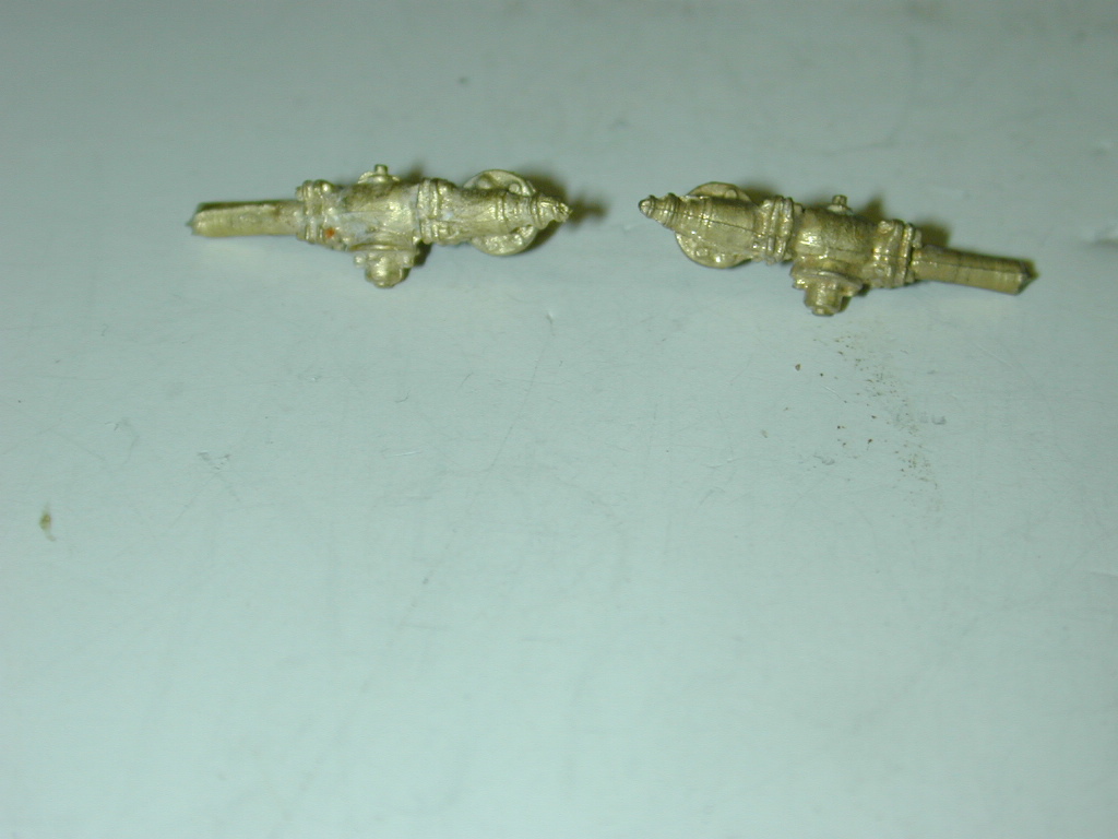
 

Next query:


Can someone ID the appliances just above the walkway (and forward of the pumps) on this Ten-Wheeler.  I'm having trouble ID-ing them, even with looking at my Loco Cyclopedia:


Original Post

Replies sorted oldest to newest

1) I've always heard them referred to as "walkways".


2) Material depends on the locomotive, and the manufacturers material use. Some are diamond plate, some are expanded metal, some are plate with oval or round holes.


3) the only "appliances" I see are right above the rear of the cylinders, and appear to be the two boiler checks for water in-put from the two injectors. If that is what you are referring to.

Thanks HW!


I'll make the walkways out of the usual flat brass.


There's an "appliance" connected to the boiler just above the ladder, the other 2 are on either side is to the right of the sand line, just above the walkway.  There's a 2 steps  just above these 2 and to the left of the sand line.


Looked at the enlarged photo again and it looks like what I thought was an appliance to the left of the sand line is just another step.


I bought some check valves from SPL (B-301):


that I was hoping to use, but I'm not sure which one it is in the photo of the steamer.

Last edited by Bob Delbridge

For what it's worth, appliance location/mounting varied over there many years of steam locomotive design development. In the early part of the twentieth century, mounting the big heavy cross-compount air compressors on boiler studs (i.e. attached directly to the boiler shell), on either side, was accepted practice. The Elesco feed water pumps and large Worthington BL feed water pumps/heaters where also mounted on boiler studs, usually on the Fireman's side.


During the later development of larger, more modern 4-8-4s and articulateds, (say late 1920s thru mid/late 1930s) the higher stresses of boiler mounted heavy appliances was recognized, and FRAME mounted heavy appliances became much more popular. Some railroads (AT&SF) even mounted a second cross-compound air compressor under the cab, mounted to the rear frame.

I've always seen and heard them referred to as "running boards." That's how they're referred to by 49 CFR 231.17 as well (http://www.law.cornell.edu/cfr/text/49/231.17)


There is a space between them and the jacket, but it would be almost undetectable in O gauge.


If piping needed to go through them, a hole would be cut. Thickness depends on material used--some were made of wood that might be a couple inches thick


The "appliance" just above the ladder appears to be the blower line.

Last edited by smd4
Originally Posted by Bob Delbridge:
I bought some check valves from SPL (B-301)

that I was hoping to use, but I'm not sure which one it is in the photo of the steamer.

The engine in the photo uses a different style of check valve than the ones you purchased.


The check valve is at the end of the diagonal pipe that slopes down toward the front of the engine, between the steam dome and the sand dome. It flattens out between the two sand lines before terminating in the check valve. 

Last edited by smd4
Originally Posted by Bob Delbridge:

Thanks Steve, I'll have to keep digging to make sure I put the right appliances on the engine.  I've got more books to look thru and use my other steamers for reference.


Finding detail parts that reflect what I see on the engines is difficult and sometimes impossible, just have to keep trying

You can certainly use the check valves you have! But yes, finding detail parts is getting harder and harder. Is PSC still making them?

The running boards (or walkways) I have seen on better detailed models and prototypes were mounted on brackets and the brackets were mounted to the boiler or boiler jacket.   They were just flat bar stock with bolt heads where they mount to the walkway and boiler.    I think most went down, kind of like a shelf bracket, so they are not visible above the walkway but are underneath.   


the following sort of show them, and they appear to go up from the walkway - these references ar the MR Steam Locomotive Cyclopedia:


Page 19 - (or loco 19) diagram in lower left

Page 62 - photo in lower left of the russian decapod

I have a cab forward with running boards drilled like that.  If you do not have a computer controlled mill to do the drilling, be sure to have the phone number of a good psychiatrist ready.


Appurtenances are easy.  You need water, so you have injectors and check valvea.  You need air, so you have pumps and tanks.  You need sand, so you have pipes and valves.  All the rest is lines supplying steam to actuate pumps, feedwater devices, whistles, bells, etc.


Feedwater heaters are a separate subject, but usually small locomotives just have injectors.  I think we did all this in an old edition of OGR.  Bob Hundman gave us permission to use a drawing of a USRA Pacific, and Myron color-coded the appurtenances.  I did the text.

Bob,

I don't have any old OGR issues, but I do have all the entire collection of Mainline Modeler mags.  Is there also an article in one of them that would help?


I worked as a draftsman from 1969-1976 at a local machine shop.  I went thru an apprenticeship and as part of it I did almost 6 months time as a machinists helper.  I recall a cone-shaped piece I drew for a 1/12 model of a wind tunnel we built for NASA Langley (in competition with Ames Laboratory in CA to see who got the job to build the full-scale wind tunnel).


The cone was about 12" long with flanges on each end and seems like there were well over 300 holes that had to be drilled in the cone.  After about 2 days learning how to use a milling machine with an indexing head they let me drill the remaining holes in it (the machinist was going on vacation).  That was gratifying to accomplish that task, and that was without a computer aided machine!


But in 1/4 scale I think I'll use flat brass stock with no holes, I don't need any more Dr. visits.

Post
×
×
×
×
Link copied to your clipboard.
×
×