
Using Fastrack and attempting to raise one from one level to the next. About 8-9 inches between the two.
What is a reasonable distance to use for a comfortable grade going up and a return trip down?
|
|
Using Fastrack and attempting to raise one from one level to the next. About 8-9 inches between the two.
What is a reasonable distance to use for a comfortable grade going up and a return trip down?
Replies sorted oldest to newest
A very good grade is 2% or less. Work to 3% of even 4% with limited trouble.
3% = 100 X 8"/x (x) is the distance you are asking for.
3x = 100 X 8
x = 800/3
x = 266" divided by 12" per foot. 22' 2" Up and another 22' 2" down.
Never saw that formula before - it works well though in giving you the exact distance needed to complete incline and decline. I always went with: if you want a 3% incline - the track is raised 3 inches for every 100 inches; if you want a 2% incline the track is raised 2 inches for every 100 inches etc. etc. etc.
Good luck Santa Fe! I'm about to construct an incline/decline too.
Thanks Mike (and Paul). If the 22 foot calculation is correct, I don't think I have enough
room to do it. Maybe next year I will try a helix!
4% grade. (My layout has 3.8% grades).
4% = 100 X 8"/x (x) is the distance you are asking for.
4x = 100 X 8
x = 800/4
x = 200" divided by 12" per foot. 16' 8" Up and another 16' 8" down.
Cut the rise to 6"
4% = 100 X 6"/x (x) is the distance you are asking for.
4x = 100 X 6
x = 600/4
x = 150" divided by 12" per foot. 12' 6" Up and another 12' 6" down.
My layout is relatively small. 12' 8" X about 10' excluding the closet yard area, first track layout.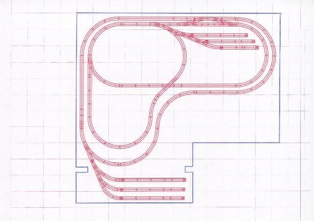
As mentioned before the grades are about 3.8% between 12ft. and 14ft of run. Note that the curves are part of the grade.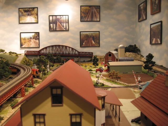
Camera walk around
Additional pictures.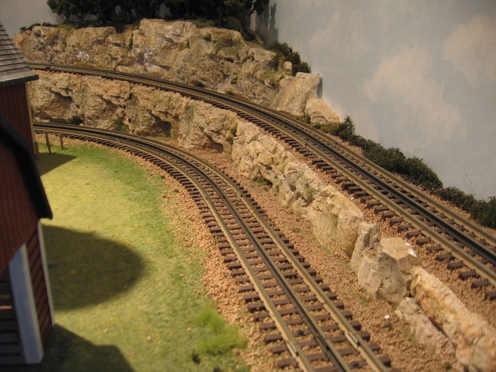

Deck bridge grade with a couple of curves.


There is not a lot of flat on the outer loop.
Best wishes with your project.
![]() Mike
Mike ![]()
Mike....that looks great. Can you come do mine?!!!!
The only way I might get it to work is to make the grade rise up to a half dogbone and then come back down the same way. Going to buy more foam from Lowes and play around this weekend with it.
If you use the Woodland Scenics grades (which I recommend), a 4% grade will give you 4" of rise in eight feet (eight feet is 96" - close enough to 100). So a 4% will need 16 feet to clear 8 inches of rise. To get to 9" of rise you will need 18 feet, to get to 10" of rise would require 20 feet.
Sounds like this will be closer to getting by within your limitations.
My previous layout had a 4% section, which was doable for my trains with a clear slowdown and speedup of course. 4% would be my absolute max limitation on grade.
My current layout is a 3% max grade (3" over 8'). With Woodland Scenics grades, that would give you 9" of rise in 24'. You could do 7.5" rise over 20' with 3% grade. Perhaps you could make it work with 7.5" rather than 8" of vertical height?
-Ken
You can also use a combination of 3% and 4% to allow you to use grade easements. This is super simple to do with the Woodland Scenics inclines and risers that come in 2' lenghts.
-- use a 2' section of 3% at the bottom of the grade.
-- use a 2' section of 3% at the top of the grade.
This gets you 4' of 3% for 1.5" of rise.
For the other 6" of rise between the easement 3% sections, you can use 4%.
-- 12 feet of 4% grade will give you a rise of 6".
That yields a total of 7.5" inches of rise in 16' total. If you have to clear 8" of rise, then add another 2' of the 4% grade (adds one inch of rise).
That would give you a total of 8.5" of rise over 18'. Hope this is helpful.
One last thought: these risers and inclines are made of foam, easy to cut and work with. You could cut a 4% 2' section down to 1 foot, to give a rise of 1/2" over 1 foot.
That would allow you to hit 8" on the nose with
- 4' of 3% easements == 1.5 inches of rise
- 13' of 4% grade == 6.5 inches of rise
8 inches of rise over 17 feet, but easy to do with the Woodland Scenics components.
Good Day,
Perhaps these web pages may be of helpful to you.
Grading Chart:http://www.centerrail.com/Fast...hart/GradeChart.aspx
Grade Calculator:http://www.centerrail.com/Fast...GradeCalculator.aspx
Regards,
Swafford
I have an around the room layout all on the same level. I decided that I wanted a hidden staging yard which meant adding a lower level. However, the modular table structure would not permit adding a lower level. So I am going to have to go up.
I wanted to do 8" too but only had about 12' between the right and left long sides of the layout. That would mean grades of 4%!
So I am raising the tables on one side 4". The track going up now has to rise 4" to the upper level, and the track to the lower table has to drop 4". Just a hair over 2%.
Jan
Mike - I really think your girder bridge incline looks fabulous! Can you tell me who makes it and where I can purchase it?
Sante Fe - if you don't have enough room for your incline try doing what I did - I raised my entire outer loop 2 inches and began from there. By doing so that will cut off 100" of space for a 2% grade.
Regards
Paul
Have you seen the grades on the approaches to the Huey P. Long Bridge in Harahan, Louisiana? These are the steepest mainline grades I ave ever seen.

I suggest that you perform an experiment to determine the steepest grade your trains will actually tolerate without slipping. It is easy to camouflage steep grades with scenery & buildings. If you settle on grades that look good but cause a track routing tradeoff, then you may regret your decision to go with what's pretty rather than what allows you the track routing you want.

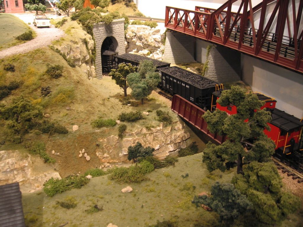
The bridge was a custom bridge from Bridge Solutions, Brian Cooper. I don't know if he is still in business. You had to contact him at the York TCA meets which would be next week Oct 16 to 19). I did a quick check of venders in the Orange Hall, no Bridge Solutions. It has been several years. I did a template of what I needed and Brian did the rest. Interesting to note that the NJ Highrails had Brian do a lot of custom work for them. They also have a listing for curved deck bridge on their website. Curves pictured are O-54.
Additional information posted on another thread.
Silk City Bridgeworks Click to access.
From their website.
Most of the parts with walkways would be listed here.
Some trains, due to weight, pulling power and magnetraction, will handle more grade than others so here is what I did. I have a large workshop and plenty of room so I took a 100" 1x6 and put 3 sections of Gargrave's straights on it and for a 2% grade I raise the end 2", for 3% I raise the end 3", etc. I am strictly pre and postwar so no drive wheels with rubber treads.
I then consisted the trains as I planned to run them, put them on the track and tested them. Since they are not getting a running start, this is a real test. Most handled 3% and several handled 4%. Those handling 4% were primarily those with magnetraction.
Jim Lawson
Surprisingly Down can be an issue also. Most of my speed control locomotives/units seem to adjust to the 3.8% grades. My Atlas SW9 require manual speed control from the Cab-1 handheld. Down is an issue with the SW9's and a longer train. Some braking before the grade is required. Note that I slow the consist before I start down the grade. Here is a consist working the grades. Click on the button to access a video.
Although not ideal, I use a 6% grade on my layout. Primeir GP35-2 can carry 16 cars up the hill at 20smph. Steam engines have less capacity, and can only carry about half that much. My new PS3 trainmaster can carry over 25 cars up the 6% grade at 6smph.
The 6% grade was needed to go to my upper mainline loop which is 16" above the lower tracks. You could use some temporary risers to create the steeper grade to see how your engines do, and use that type of experiment to decide on the look and function of a steeper grade.
JoeK
At one point, I has a 7% grade on my mainline. Certain engines would get hung up at the top of it. I decided, for my operational sanity, that 7% grade had to be reduced. Ultimately, I think I am around 3-4% and trains are running a lot better.
The lead to my hidden storage yard has a 5.5% grade. The switcher can take 9 cars down, but only 4 back up. That's OK, we get some operational reality into the mix.
If you can get to a 4 or 4.5% grade you should be good to go, particularly if you have a straight run up.
George
Another trick is to figure where your upper level track is going to cross over the lower level track. Then lower the lower track a little. Every inch lowered is that much less of a grade for the upper level. Russ
Thanks everyone for the good suggestions. I didn't have enough room to make it work so I am going with plan B....raise the entire inner loop by 5-6" so that it will safely cross over the lower level but not have any grade issues to worry about.
Mike,
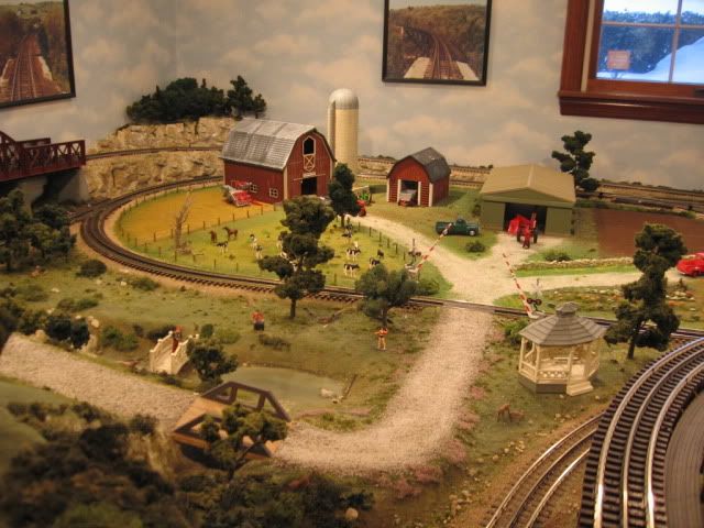
I don't want to hijack this thread, but I like your layout and might consider scaling down my design somewhat as a result. I'd like to clarify a few things because I don't totally understand the rise requirements.
Although you are using an 8" rise, there doesn't appear to be an operational need for this. It appears that the degree of track separation is dictated by the tunnel portal inside heights and from what I found on the MTH website, their portals are 5 5/8" tall inside.
That aside, I currently have 3 tracks I need to clear. I'm working with a 6" clearance, but I'm considering leaving off the plywood sub-base above these 3 tracks to give me an extra 3/4" clearance and perhaps lowering that section of track 1" for even more clearance. Two of the tracks are part of a loop that will be inside a tunnel below the cookie-cutter level above them. The crossover will be visible under a bridge. Does this all sound like it will work okay?

I had done the deck bridge with a MTH graduated trestle set, before the custom deck bridge. You could cut the difference to 6" minimal tunnel clearance. 7" worked well for me. Note that where the House sets is a few inches higher than the upper level to compensate for the top of the tunnel portal.
Another look at the tunnel allowing 1/4" for the tunnel liner and 1/2" for the plywood second level, about 6 3/4" to the 7" I measured.
![]() Best wishes with your project
Best wishes with your project![]() .
.
Mike CT
Thanks so much, Mike

Access to this requires an OGR Forum Supporting Membership
