Thanks, Steve, but I just changed the configuration of your yard/spur. I actually did do a design that matched yours, but didn’t think to ask Dave if he could bridge the corner. Then I didn’t know about all the accessories he wanted to retain. The bottom line is I think we have something he can enjoy and I hope he’ll post photos of the progress.
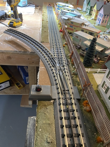
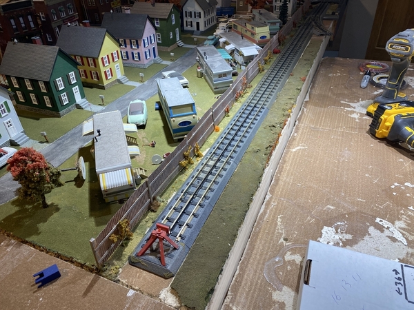
I'm waiting on switches and my sons help for the bench work but got a little done. I removed some track back to where the new plan starts. I then added the first 054 switch with a 30-10-5-3-inch straights & a bumper. The piece of 054 track hanging out is just to show the path. The 45 angle that will be under it won't be big and allows me to use 054 on the main.
Attachments
Things make more sense now that I see more of the current layout. I can see why you didn’t want to redo it all.
Dave or Steve, I failed to notice the short straight added to the original layout. Is it a 3.5? If I can't fit this, can I shorten the 10 inch in front of the 054? I won't be home today so no hurry on figuring out my mistake. Thanks!
Attachments
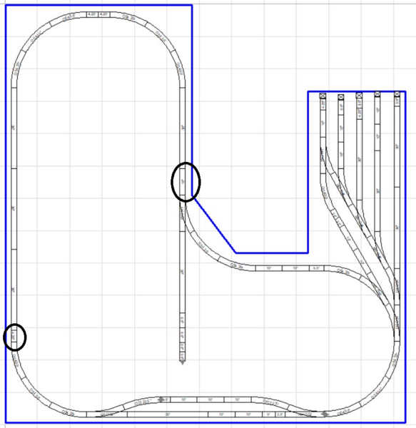
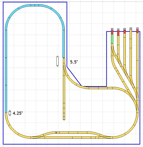
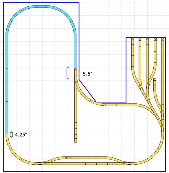
Sorry, Dave, I didn't notice it either when I added the 48" spur to the file. At Any rate, the small piece is a 4.25" straight. Unfortunately, there's no combination of RealTrax track that will directly replace the 10" straight. You really need a 5.75" track, but you can try using a 5.5" to see if there's enough wiggle room in the Gold tracks to let it all fit. The problem there is it shifts the entire section up 4.25" and you'll need to shorten the Red yard spurs. Doing that will leave just the Green 10" straight past the switch and that might not be enough room for an engine to escape. I've added a different yard configuration for you to consider, if needed.
Attachments
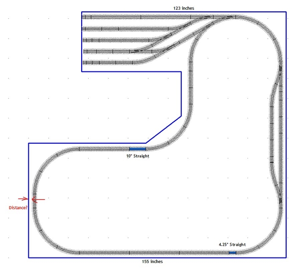
When I was working on the design, the location where I positioned the original track was a guess. My guess was the distance between the edge of the table and the edge of the roadbed (as indicated in this image) would be about 1 3/4".
Will you please measure this distance? If it's much more than 1 3/4", adjustments to the plan are needed.
In this picture, there is also another configuration for the switch yard that may allow more room for a switching locomotive to navigate around.
SCARM file is also attached.
Attachments
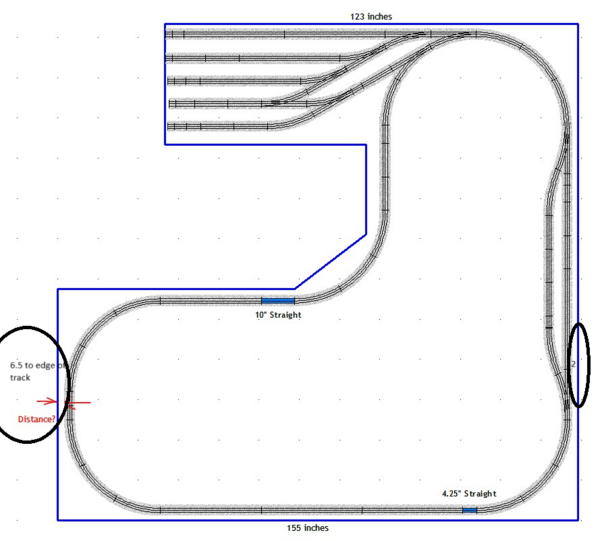
6 to the edge of the roadbed on one end 2 on the other. I talked to my son and the bump out can be 3.5 x5. At this point I have 2 054 L, 2 054 R & 1 072 Y for that area. If that doesn't work, I'll keep an eye out for another couple 054 rights. I have a few buildings to fit in between one of the spurs. I won't really know till he does the bench work.
Attachments
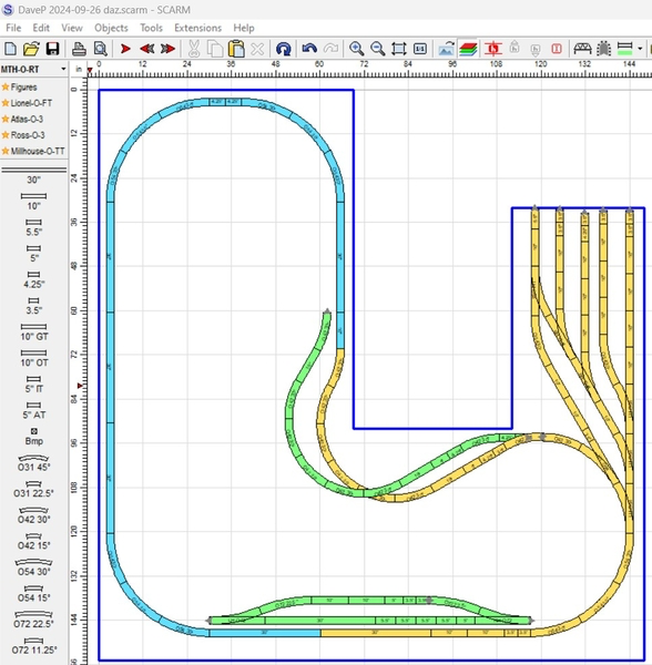
Steve, I didn’t understand in my first attempt that he didn’t want to tear up his current layout, so after he reiterated that, I color-coded those tracks in Blue so I wouldn’t change them. After I posted this version, he said he could add the triangle in the corner to avoid the curves and keep things O-54. You beat me to the next version and he liked it, so when I added the 48" spur down the middle, I didn’t notice that you added the small track on the left to fill the space along the bottom.
Attachments
@DoubleDAZ it's all good. We'll get there. ![]()
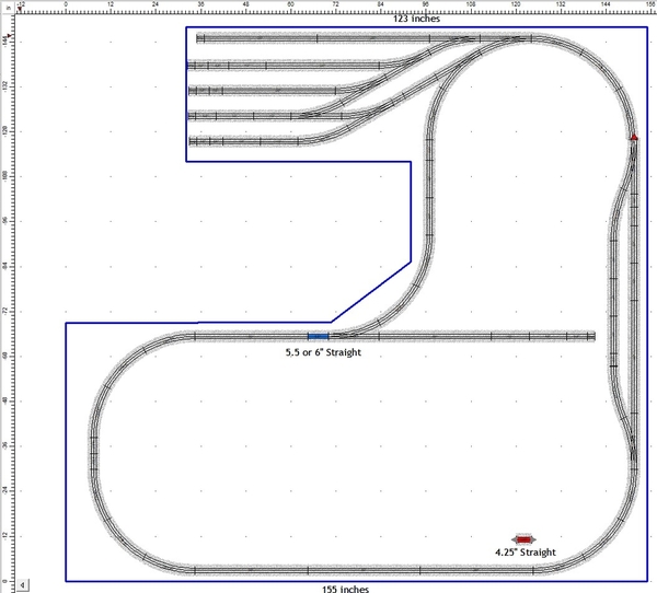
I've realigned this plan with the existing layout and removed the 4.25 Straight on the 155" side of the table. To be able to keep O54 curves, the 10 inch straight at the 45 inside corner would need either to be replaced with a custom length 6" piece or maybe a 5.5" piece would work instead. The picture below shows a 5.5 which doesn't make for perfect alignment at the opposite upper side of the curve (red arrow), but with a little skewing of the track joints it may line-up ok.
I also had to shorten some of the yard spurs a bit with the understanding that this will likely change more later.
Attachments
@SteveH posted:@DoubleDAZ it's all good. We'll get there.
I've realigned this plan with the existing layout and removed the 4.25 Straight on the 155" side of the table. To be able to keep O54 curves, the 10 inch straight at the 45 inside corner would need either to be replaced with a custom length 6" piece or maybe a 5.5" piece would work with some wiggle room to get it all to line-up. I also had to shorten some of the yard spurs a bit with the understanding that this will likely change more later.
Thanks, I'll change that 10 to a 5.5 or do a cut if I can find my chopper. I should have mentioned the distance on the far end, I have a couple of scenes and a road crossing there.
Steve, I'm curious, how does your passing siding show up connected? When I open your file, it shows as disconnected just like my photos. Did you change the default tolerance from .079" or something?
@Dave Ripp. posted:Thanks, I'll change that 10 to a 5.5 or do a cut if I can find my chopper. I should have mentioned the distance on the far end, I have a couple of scenes and a road crossing there.
I wondered why there was so much space at the bottom (or right side depending on orientation). ![]() I think it'll all fit with the 5.5", but I know RealTrax can be a bit finnicky at times. Mine was O-31 curves though, so that might have had something to do with it too. BTW, you can do without the engine escape section if you run trains clockwise and back into the yard. That will make servicing the 48" spur more difficult though. Or, if you run counterclockwise, you could drop cars on the passing siding and have another engine back them in the yard.
I think it'll all fit with the 5.5", but I know RealTrax can be a bit finnicky at times. Mine was O-31 curves though, so that might have had something to do with it too. BTW, you can do without the engine escape section if you run trains clockwise and back into the yard. That will make servicing the 48" spur more difficult though. Or, if you run counterclockwise, you could drop cars on the passing siding and have another engine back them in the yard.
@DoubleDAZ thanks for mentioning this. Yes, the passing siding as shown is about 0.2 inches longer than the parallel main. This may require some cut track, if not doing so would make the joints in the mainline too loose.
I did change my default tolerances a couple of years ago. When I did the most recent screenshot, they were set to: dx = 0.15; Angle 2.5 deg.
It's interesting that SCARM considers a 0.1 inch overlap to be less than a 0.15 tolerance. When I change it to 0.1 or less this connection is not joined. Think I'm going to leave it at 0.1.
@DoubleDAZ posted:I wondered why there was so much space at the bottom (or right side depending on orientation).
I think it'll all fit with the 5.5", but I know RealTrax can be a bit finnicky at times. Mine was O-31 curves though, so that might have had something to do with it too. BTW, you can do without the engine escape section if you run trains clockwise and back into the yard. That will make servicing the 48" spur more difficult though. Or, if you run counterclockwise, you could drop cars on the passing siding and have another engine back them in the yard.
I love the escape track, that's what sold me on the yard. I'll have some time tomorrow to play around with it. I'm sure it'll work one way or another.
Steve, got it. When I zoom in and snip the overlap, I get .11". SCARM has to look at things as either an overlap or gap, so I think that might means something like -.1 vs -.15 or +.1 vs +.15.
Dave, I agree, just not sure it will fit if you’re going to put some buildings there. You can leave out the last spur and change the switch to a curve.
@DoubleDAZ posted:Steve, got it. When I zoom in and snip the overlap, I get .11". SCARM has to look at things as either an overlap or gap, so I think that might means something like -.1 vs -.15 or +.1 vs +.15.
Dave, I agree, just not sure it will fit if you’re going to put some buildings there. You can leave out the last spur and change the switch to a curve.
The buildings will be between the first 2 I'll work that out latter. I had a precut 5 7/8 straight in my track box. That should get me close. That also lengthened the siding to 55 inches about 50 usable.
Yeah. The space should be 5.75" (10-4.25), so that piece should fit right in. Saves you having to look for the cutter. 🤣
Sorry for the long pause I've had some medical issues, so I needed my sons help. Ryan came today and finished my bench work. The 3x 5 bump out ended up a 4 x 4 so we'll see how that works when I get it cleaned up and put some track down.
Attachments
It's been a while since I posted. Some things worked out and many will be different. I ended up moving the trailer park and some houses which was a no go originally. I didn't like the short passing siding as I wanted a reasonable length train to fit. After much debate I've ordered a 072 left and 072 1/2track to start it farther back. Once I get the track I'll play with where it can tie in. For today I removed a 30-inch section for the new switch. I'll update when my new parts arrive.
Attachments
Dave, I agree with you that passing sidings need to be plenty long. My original sidings were too short, so I ended up with one long one.
Dave, thanks for the update. Glad you found a way to fit a longer passing siding. I imagine it's also a good feeling to be making physical progress on the layout again. ![]()
@SteveH posted:Dave, thanks for the update. Glad you found a way to fit a longer passing siding. I imagine it's also a good feeling to be making physical progress on the layout again.
Thanks Steve, I was feeling guilty over the effort you and Dave put in and my abrupt stop. I'm generally a scenery over track guy but the siding will end up giving me both.
Installed 1 072 switch a 10 & 5 inch where I took out 30 inch for start of passing siding. The rest of the track won't be here till Tuesday slow shipping. The building on the left will not be there once I get the track in.
Attachments
Dave, it’s good to make the change now as opposed to waiting and having to expend a lot more effort.


