PS2 light circuits will drive a 60ma filament bulb or several LEDs. PS3 are oem led..will they handle additional LEDs?
Replies sorted oldest to newest
They run 4 on a circuit in some applications. Just remember if you burn up the chip controlling a light function on PS-3 it won't be repairable by mortals. G
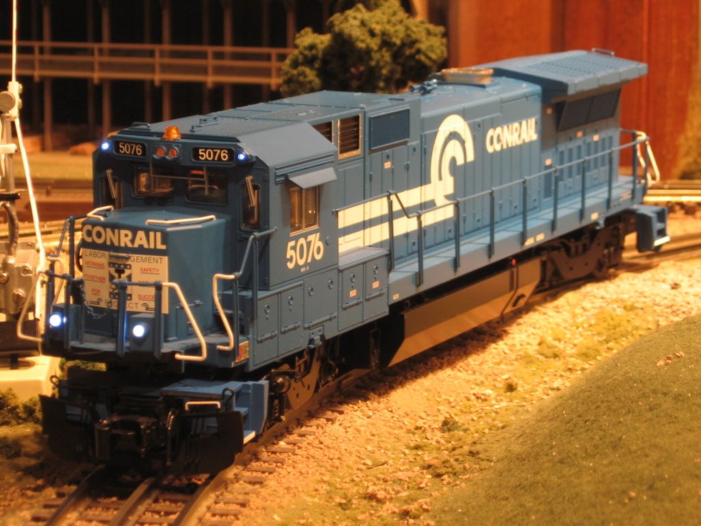
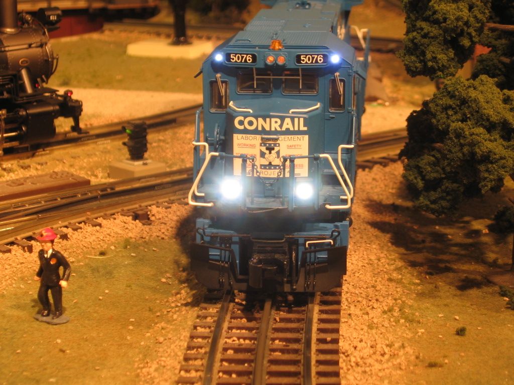
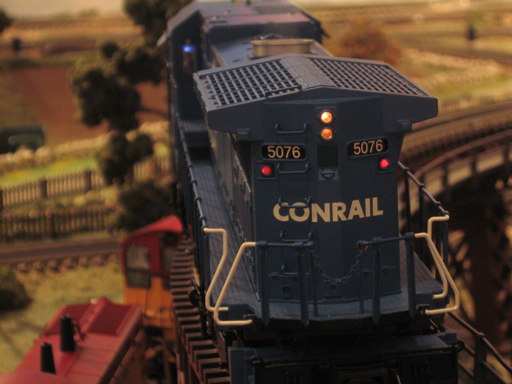
Thanks GGG..i was thinking of adding a ditch light set to a GP35 PS3...dimly lit,off white to yellowish 10 ma draw with proper resistor off from the headlight circuit. I should look at the PS3 pinout..maybe an unused output there? The lead Guilford engine in the middle of this video would be the candidate.
If it does not have ditch lights I would get a set of connectors to add the connector for Ditch 1 and 2 then get SF that has ditch lights. G
Just checked soft keys...a DCH key![]()
I think you need LDI.
you're right..dch is chrono...duh...i do have unused LMK soft key..don't care about ditch lights flashing.
I think pins 5 and 39 should be tried anyways. Just maybe they will be on as it sounds like you don't care about controlling them?
Look at page 16 diagram of the PS3 instructions for the other pin outs.
G???
PS-3 LED for Markers are still series wired like PS-2. LEDs for direction lights or Number Boards are parallel wired when doubled. G
Thanks GGG and EJOE...can i assume the LMK is current limited and no resistor required?
I would not go adding extra LED's to the PS/3 light outputs. As George says, if you cook them, they're gone. I live in hope that at some point we'll get some info on the drivers used to fix common stuff like this, but not to date. ![]()
Since PS/3 has outputs for both front and back ditch lights, you have plenty of choices of dedicated light outputs.
John,
Wouldn't you have to have a SF to support them? My RK GP20 (20-20090-1) has no wires in the 5 and 39 pins and no key for them in the remote. No markers, either.
Yes, you'd have to load a different sound file. I solve the wire issue by using wires left over from diesel upgrades. I also have the contacts for the 1mm connectors, but they are somewhat of a PITA to crimp, it's hard to get them into the crimp tool they're so small! ![]()
These lights, LED's, high on the cab were simply hooked to track power with an appropriate resistor. If my foggy head remembers correctly, the ditch lights and rear markers were also added to track power with an appropriate resistor. Ditch lights don't flash. The original SAW GenII board was scrapped, and replaced with a more robust EOB drive board that had no provisions for fancy lights. (2)LED's hooked in parallel to I think a 1000 ohm resistor in series to track power. I have a foggy head, you would need to verify this. The EOB board was installed by Weaver, came back with all the fancy lights disconnected. A call to Atlas, yielded the information needed to connect the lights, as mentioned. Anthony K's Atlas Dash 8 40


Mike CT posted:Ditch lights don't flash.
Say what? Since when?
gunrunnerjohn posted:Mike CT posted:Ditch lights don't flash.
Say what? Since when?
Since I fixed it last. EOB don't flash. ![]() I think John has a flash(board). Those early SAW GenII boards were interesting, too bad they didn't work well. They also turned the head light/tail light off when the engine idled.
I think John has a flash(board). Those early SAW GenII boards were interesting, too bad they didn't work well. They also turned the head light/tail light off when the engine idled.
I think I misunderstood your comment. You're saying in your installation they don't flash, I guess I can buy that. ![]()
Since he's dealing with a PS/3 board, with the right sound file, he has full functionality of front and rear ditch lights, including flashing with the horn.
gunrunnerjohn posted:I think I misunderstood your comment. You're saying in your installation they don't flash, I guess I can buy that.
Since he's dealing with a PS/3 board, with the right sound file, he has full functionality of front and rear ditch lights, including flashing with the horn.
God bless him and PS/3. The world is a better place. ![]() Primary part of my comment was that the LED's could be hooked else where.
Primary part of my comment was that the LED's could be hooked else where.
Onward, Mike CT.
Well, yes. You can power them from a lot of sources. If you want ditch light full functionality, then the options are a little more limited. ![]()
I was hoping there was a unused molex( LMK ) for my steady on ditch lights. I f not i will use track power (18vac) run the 2 LEDs in series back to back with an appropriate res.![]()
Just to confirm: i do have the unused molex from pin 31![]() It is yellow with blue and purple leads. My ? is..do i wire 2 LEDs in parallel or in series? Can i assume no resistor required?
It is yellow with blue and purple leads. My ? is..do i wire 2 LEDs in parallel or in series? Can i assume no resistor required?
This is the engine: http://mthtrains.com/20-20200-2

Soon i hope...

Attachments
I would expect the LED circuits to be designed for a single LED. I don't have a big enough experience base with factory PS/3 to know if they have multiple LED's on a single output, I don't remember ever seeing more than one LED on a circuit.
I do wonder how they would handle the dual headlights of something like a GP-9, so there might be a way to use more than one LED.
GGG posted:PS-3 LED for Markers are still series wired like PS-2. LEDs for direction lights or Number Boards are parallel wired when doubled. G
!
Engineer-Joe posted:GGG posted:PS-3 LED for Markers are still series wired like PS-2. LEDs for direction lights or Number Boards are parallel wired when doubled. G
!
Thanks..somehow i missed that. "Series" it is![]() . Last question.. no resistor required as i am thinking this is a LED current controlled circuit?
. Last question.. no resistor required as i am thinking this is a LED current controlled circuit?
gunrunnerjohn posted:I would expect the LED circuits to be designed for a single LED. I don't have a big enough experience base with factory PS/3 to know if they have multiple LED's on a single output, I don't remember ever seeing more than one LED on a circuit.
I do wonder how they would handle the dual headlights of something like a GP-9, so there might be a way to use more than one LED.
Thanks GRG..pin 31 in above schematic does have a (X2) beside it so i am assuming 2 LEDs..Hope i am right![]()
Learned something new today, so we can parallel at least two LED's for the PS/3 outputs. ![]()
gunrunnerjohn posted:Learned something new today, so we can parallel at least two LED's for the PS/3 outputs.
Specifically according to GGG PS-3 LED for Markers are still series wired like PS-2. LEDs for direction lights or Number Boards are parallel wired when doubled.
The FETs can handle 2 parallel LED. The Marker is 2 in series. LNB, Int light and HL are normally 2 LED parallel harness. Frankly I do think LNB are 2X 2 LED harness. So 4. G
I'm curious to know how they adjust the current to a variable number of LED's on the outputs...
Ditch lights installed using track power. Back to back LEDs (wired in series) with a 10k resistor. On a 2 rail Premiere GP35 track power is the wire nut tan wire bundle and wire nut black wire bundle. I will probably add marker lights later using the dedicated pinouts.
Attachments
I don't think you're using a 10K resistor, care to correct that? ![]()
gunrunnerjohn posted:I don't think you're using a 10K resistor, care to correct that?
It is a br/bk/bk/r/violet...
The I can't imagine the lights wouldn't be nearly that bright with a 10k resistor. You're talking about less than one milliamp of current. I just tried two white LED's with a 10K in series, they were very dim, those sure look a lot brighter to me.
Did you use 18vac actually closer to 18.4 vac (Z1000)? I grabbed this resistor with the intentions of working my way down and was surprised it even worked. Harbor Freight reads 9.93 on 20k scale. LEDs are 3mm warm..ebay specials.
I am using a Z-1000 at full voltage. Obviously, the picture makes them look brighter than they are. ![]()
gunrunnerjohn posted:The I can't imagine the lights wouldn't be nearly that bright with a 10k resistor. You're talking about less than one milliamp of current. I just tried two white LED's with a 10K in series, they were very dim, those sure look a lot brighter to me.
I read .671..but is this valid because ac>dc circuit? Anyway they look dim and dirty like the real thing.![]()
I think I was just fooled by the picture in the dark. Although it's an AC > DC circuit, if the LED's are in series, there is only pulsing DC in the circuit.


