I'm thinking of buying one of the newer Menards buildings that requires the power supply. Except I don't want to use that power supply. I'd rather not use a spot on one of my power strips for it. What I plan on doing is using one of my buck converters and a diode and set it to 4.5V DC with power coming from my lighting circuit. I've got some questions for the Forum about this. 

1. What is the exact size of the plug on the DC walwart that usually powers the buildings? I'll order one from Digikey and connect it to the converter.

2. Will a diode in front of the converter be sufficient or should I use a bridge rectifier?

3. Should I add another capacitor (other than the one on the converter) for the Menards LEDs?

-Roger

Original Post

Replies sorted oldest to newest

If you use a diode, you get half-wave rectified power, so in order to get properly filtered DC for the board, you'd need a much larger capacitor to smooth the ripple.  The bridge gives you full wave rectification.  I'd start with a 470uf 35V capacitor and a bridge rectifier.  The higher the load current, the larger the filter capacitor should be.  Below is the difference in what the capacitor sees half-wave and full-wave.

Half-Wave vs. Full-Wave Rectification

Well, that's an open book.   There are situations where a diode is the right choice.  Specifically, for my Super-Chuffer, I use a diode and not a bridge.  I use that for a good reason, I want a common DC ground that is referenced to frame ground.  If I use a bridge rectifier in the DC supply, the DC ground is NOT frame ground, that complicates interfacing to other components when installing a Super-Chuffer.

I guess I've lucked out in many of my attempts then. I've got converter boards connected to just a diode to control some of my accessories like my Oil Drum Loader and Freight Station. The voltage in my accessory circuits was too high for them to operate at prototypical speeds. I had diodes handy and I had the converters handy. Connected them up and they worked fine. In reality, I probably just lucked out.

Roger

Since you presumably have the building in hand, measure the center-pin diameter of the power jack.  It will most likely be 2.1mm as GRJ suggests.  The other less likely possibility is 2.5mm.  From the suggested adapter on their website it looks like a 2.1mm but looks can be deceiving!

vx_el4005wh

DigiKey will certainly have the loose plug, example:

http://www.digikey.com/product...A/CP3-1000-ND/992136

PP3-002A_sml [2)

But with shipping at maybe $3, I suggest you look around the attic for an unused wall-wart with the same 2.1mm plug and simply cut off the cord/plug and re-use that.   Garage sales (albeit wrong time of year) or Goodwill stores have wall warts for maybe 50 cents and you're only interested in the plug-cable so should be easy to find...


Attachments

Images (2)
  • PP3-002A_sml (2)
  • vx_el4005wh

Mike, I posted an identical one that's half the price, including shipping, and even cheaper in quantity!  Did you read the post above yours?

$4.06 for the first one, and $3.06 for any over quantity one.  That Amazon reference is a Far East company, so you won't get that one any faster, you'll just pay over double for the privilege of buying it from Amazon!

eBay: 261876960293 


So this being a discussion forum, we now have this alternative:

ac dc regulators distributed

One thing about the AC-to-DC module is that input capacitor is rather tall.  For track-side accessories, stations, buildings, etc. this is usually not a problem but worth pointing out; it can be a consideration if using one of these modules within rolling-stock.  Also shown in diagram above is something GRJ alluded to earlier.  Once you go thru a bridge rectifier you "lose" a common electrical return (ground).  So the "-" sides of each module are actually different signals as represented by different colors.  For the application at hand (powering a variety of independent accessories) this is irrelevant but I think worth a mention.

So another alternative is to use the less expensive DC-to-DC module.  The input capacitor is much shorter so the module may be easier to find a home.  The idea is to use just one bridge rectifier to convert AC to unregulated DC.   Then each DC-to-DC module converts the shared unregulated DC voltage.  You'd simply add a common capacitor to "bulk up" the input capacitance.  Note that the DC-to-DC modules have smaller supplied input capacitors than the AC-to-DC modules.  As an aside, note that some 99 cent eBay modules have 100uF input caps, while others have 220uF input caps (same price).  Given a choice I'd get the 220uF.

dc regulators distributed approach

Yes, a bit more soldering to put together the external shared bridge rectifier and capacitor.  And there may be wiring considerations on what power signals are available where on a large layout.  In this case the DC common is truly a common signal (shown black line) across all modules since there is only one bridge rectifier.  Again, this is not an issue for the application at hand but is worth a mention.

Attachments

Images (2)
  • ac dc regulators distributed
  • dc regulators distributed approach
gunrunnerjohn posted:

Stan, the only way the DC common is truly common for the DC-DC modules with the added bridge is if the accessory winding is totally isolated, an important fact to realize if you're trying to use an accessory winding on a transformer connected to other accessories or tracks.

I may be misunderstanding but if by "modules with the added bridge" you mean the $3 AC-to-DC module, then you'd have to physically tie the "DC-" outputs to each other to make a true DC-common.  This would mean and isolated AC accessory winding feeding each AC-to-DC module.  I can't imagine anyone doing this.

I don't claim to know much about electricity but these methods seem an awful lot more complicated than using a simple plug and play power supply that we offer.

I just wanted to remind everyone that the electrical within our buildings is specifically engineered to accept 4.5 volts. Anything else can fry the wiring. 

-Mark the Menards Train Guy

Mark

Not knocking the power supply you sell,but if you have multiple buildings and a large layout,it is a lot of wires to run and things to plug in. Sometimes the building is farther away from an AC plug than the cord length. The Buck converter can be run off any toy train transformer at any voltage over 6 and will power multiple buildings. It would be helpful to have an optional polarized marked input so 2 wires can go in instead of a jack,or at least provide a conversion jack for transformer operation. . If you see the link I gave in the last post above,there are a lot of other uses for the converters.. I used to make my own linear power supplies with LM350 chips and 7805 chips,but if they sell these converters at $2 each, it is not worth the effort. Just turn the screw until 4.5 volts is on the meter.

Last edited by Dale H
Menards posted:

I don't claim to know much about electricity but these methods seem an awful lot more complicated than using a simple plug and play power supply that we offer.

Agreed.  But the OP initially made the point that he does not want to use an AC-outlet power supply for his Menards bldg.  Maybe you can confirm that your Menards plug-and-play power supply is indeed a 2.1mm sized plug?

I think that it is "an awful lot more complicated" ......for one building.  I think the new Menards buildings are terrific, but having to have outlet space for each walwart for each building would be a deal breaker for me. These converters can be dialed in to specific voltage outputs and are more compatible with the system I use to power accessories.

So answering a question that no one has asked , here's a representation of the OP's original configuration. 

dc regulators distributed approach no bridge

By using a single diode (or a single diode feeding each module), the AC common from the accessory transformer is the same as the DC common on the inputs and outputs of each regulator module.  In this application, the log loader, station platform, and Menards building are independent loads that don't electrically or functionally interact with each other.  So all this blather about commons (mostly my doing) is just that!

IMO the big picture is that more and more accessories are DC devices as DC LEDs replace incandescent bulbs, DC motors replace AC mechanisms, and so on.  And more guys are taking matters into their own hands realizing that driving an accessory mechanism at 5V, 6V DC or whatever you want is more realistic than the take-it-or-leave-it behavior at 14V AC accessory voltage.

It's fine that accessory manufacturers provide the DC wall-wart adapters but if you have several accessories requiring different voltages and each with its own wall-wart, it's worth thinking about a DIY approach.  These eBay regulator modules are inexpensive and while soldering, wiring, etc. is not for everyone, it can provide flexibility and options that didn't exist just a few years back.

Attachments

Images (1)
  • dc regulators distributed approach no bridge

Well, my new Menards building (burned engine house) arrived yesterday and my electronics arrived today. Soldered it all together and it works great. I've got the buck converter (with it's attached cap and bridge) dialed to 4.5 volts and it's all good to go. My only complaint (with the building itself) is that it gives you a choice of lighting modes and I liked the mode where the embers glow brightly and then dim and repeat. More prototypical. However, when you cut the power, it has no memory and goes back to full on.  But as with all the new Menards buildings, it looks very cool.


Roger

Out of curiosity, when you power it up how do you change the mode to the one you like? 

One of the benefits of going the DIY approach using insanely low-priced eBay electronic modules is ability to customize your accessories for not much coin.  For example there are timer modules that close a relay, say, 1 second after receiving power.  So this could automatically "push" the mode button if that's how you change the lighting mode on your fire house.   I can't imagine anyone going thru the effort though....

Stan,

Funny you should ask about the mode change.  When I opened it up, I couldn't find any directions, but next to the female plug receptacle was a button and a small slider switch. I assumed that the slider turned power on and the button changed modes. I couldn't test it until the male plug I ordered arrived today and I could wire it up. There are 4 modes. Off, Full on, blinking and.....the fade dim I described above. Default is full on. 

And yes.....those Chinese modules are cheap and (so far) high quality. As for that timer with a relay...I played with one a few months ago. I was trying to Rube Goldberg some ditch lights. I asked Dave at Evans to slow one of this flasher pairs down to a more realistic flash pattern. Then I tried to connect them to one of those timers which was in turn connected to a PW whistle relay to trigger it. Fun playing with it, but I couldn't get it to work, so the "flashers" I installed on a Williams F3 are now permanently on marker lights. 

Roger

ROGER1 posted:

I think that it is "an awful lot more complicated" ......for one building.  I think the new Menards buildings are terrific, but having to have outlet space for each walwart for each building would be a deal breaker for me. These converters can be dialed in to specific voltage outputs and are more compatible with the system I use to power accessories.

Actually one power adapter powers 3 Menards buildings.  You get the one with 3 leads instead of the single one.  So you don't need a separate power adapter for each building.  One does 3 buildings.

.

So here's the FRM01 cycle timer module (discussed in several earlier OGR threads) which is about $7 shipped from Asia on eBay...or a bit more on Amazon.

When power is applied, the module delays 1 sec, then closes the relay for 1 sec.  It repeats this cycle twice.  So if the relay COM-NO contacts are placed across the Menard's momentary button, it should "automatically" put the lighting into the desired mode each time you turn on the building.

Or you can continue to imagine GRJ writing the code for an Arduino.

Nothing is so easy as the job you do just for fun at 5 in the morning after sleeping off a christmas feast.  

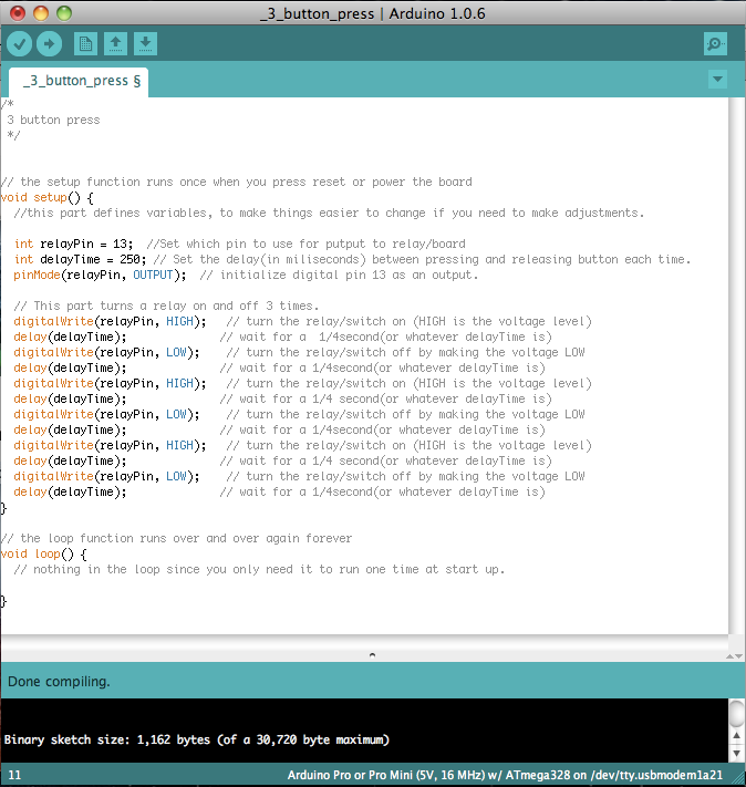
Anyway, I don't have a board with me to test, but this would be the code for an arduino to press a button 3 times.  for simplicity you could connect a 99 cent relay module to the arduino, but if size is a concern a separate relay with a transistor might be the way to go.  or if you want to ger fancy you could probe the building's board with a meter and figure out if the button is just closing a high/low contact, and at what voltage, and connect that right to the arduino.  If it were my project, that's the route I'd take, perhaps with an optocoupler as a buffer between.  

If this seem like something worth pursuing further than random musing, I can provide more information.  

I chose the ProMini for size, and cost, being less than $2 each.  As a note I tend to use 5v boards, but they do come in 3.3v versions.  If I were choosing for this project, I'd still go with the 5v version, set my buck converter at 5.0v and place 1 diode in line before the building's power-in to drop it to 4.4v which should work fine.  

JGL

Add Reply

Post

OGR Publishing, Inc., 1310 Eastside Centre Ct, Ste 6, Mountain Home, AR 72653
800-980-OGRR (6477)
www.ogaugerr.com

×
×
×
×
Link copied to your clipboard.
×
×