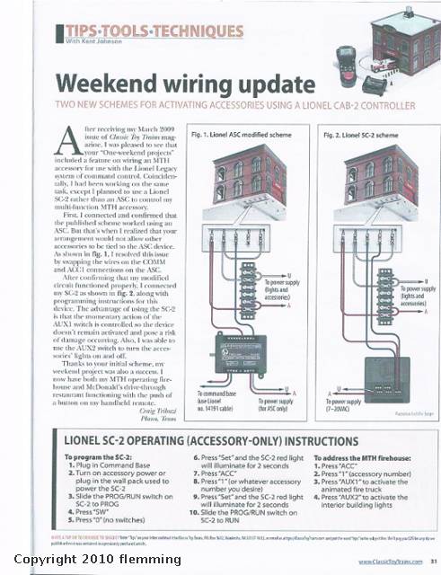
In Fig. 2 in the picture Do i need (2) AC transformers wires going from the terminal strip to U and A on the transformer and wires going from the SC-2 to U and A on the transformer or do i use the wall power pack that came with the SC-2. I  have no switches on my lay out


Last edited by flemming
Original Post

Replies sorted oldest to newest

That's better!


You can use a single transformer for both of the power A and common U connections.  All of the relay contacts (except for channel 1) are totally isolated from the power that powers the SC-2. 


There is a mod which involves cutting the common that goes to the first output to isolate that relay as well, this is done to allow Fastrack switches to be used on channel 1.


For your purposes, any channel except channel 1 will work fine and there will be no conflicts with a single supply.

I use phone wire to wire the fire station 20-22. 


The SC-2 is a powered switch therefore it needs power to operate, it's not mechanical.  I use the wall wart to power the switch.  Then you have to power the accessory from the transformer.  You can power both from yourtransformer I just don't do it.  The SC-2 booklet should explain this.


Doug

is it solid or standed wire
 
Originally Posted by Doug N:

I use phone wire to wire the fire station 20-22. 


The SC-2 is a powered switch therefore it needs power to operate, it's not mechanical.  I use the wall wart to power the switch.  Then you have to power the accessory from the transformer.  You can power both from yourtransformer I just don't do it.  The SC-2 booklet should explain this.


Doug


Originally Posted by flemming:

If i ran the 6-12053 Accessory Power Wire from a fastrack to the Auxiliary on the SC-2 will it power the SC-2

Yep, it'll work just fine.  I have two of them powered from the track in that manner.  Just make sure to connect the track common to the correct terminal.


Note that you can't run Fastrack switches from channel 1 unless you do the mod that cuts the ground between the aux power input and the first channel.

I am going to try to follow the diagram above in fig 2 i hope everything works out just waiting on my 18-4 Power Cable (18 AWG Wire) from usLEDsupply it was shipped today via usps first class mail
 
Originally Posted by gunrunnerjohn:

No problem in that case.  Just remember that track common is also common on input #1 if you have a separate power supply for accessories. 


Last edited by flemming

All the channels are basically created equal, with the exception of the common from the power being wired to channel 1.  I actually cut that away on all my SC-2 boxes so all the channels were identical.  From the manual, it has three programmed settings.


The SC-2 is designed for three operating modes:


1. Control four switches through the left and center terminal blocks. Control two momentary and two on/off accessory functions through the right terminal block.
2. Control six switches using all three terminal blocks.
3. Control six momentary and six on/off accessory functions using all three terminal blocks.

I also have the LIONEL covered lighted bridge and the  MTH blinking Arch bridge do wire them to the accessory  terminal  block 2 for  accessory 2 just like the diagram on page 19 of the SC-2 manual. since the fire station is it going to be connected to accessory terminal  block 1 for accessory  1 on the SC-2 i dont understand this part on page 20 of the SC-2 manual  id#2 automatically assigned does this mean i press 2 for the LIONEL covered lighted bridge and the  MTH blinking Arch bridge the aux 2 to turn on and off the lights since the fire station  is going to be set as accessory 1


Originally Posted by gunrunnerjohn:
 
All the channels are basically created equal, with the exception of the common from the power being wired to channel 1.  I actually cut that away on all my SC-2 boxes so all the channels were identical.  From the manual, it has three programmed settings.


The SC-2 is designed for three operating modes:


1. Control four switches through the left and center terminal blocks. Control two momentary and two on/off accessory functions through the right terminal block.
2. Control six switches using all three terminal blocks.
3. Control six momentary and six on/off accessory functions using all three terminal blocks.


Last edited by flemming

You can power two accessories from one channel as you say.  Aux1 will activate the momentary to common connection, and Aux2 will toggle the on/off connection.  These can be independent accessories, noting that they share a common return.  Both of these accessories would use the same accessory # in the configuration, and they'd be wired to the same three connection block on the SC-2.


The accessory # are sequential, each of the connection blocks on the SC-2 is numbered separately, however the momentary and on/off connection to a single connection block share the same accessory #.


I'm not familiar with those two particular accessories.  As long as one of those accessories requires a momentary contact and the other requires an on/off contact, you have it correct.

Do all  accessories need there own external power if the SC-2 is only used for accessories and no switches


Originally Posted by gunrunnerjohn:

In his picture, he obviously has this programmed for all accessories.  If you have four switches and two accessories, the right hand two terminal blocks are Acc #1 at the top and Acc #2 at the bottom.  The switches would use the four left hand connection blocks.


Yes, you need the external power if you're not using switches.  The SC-2 was designed in the era where the 022 and it's cousins were king, so even Fastrack switches require a separate PS.  I'm sure stuff like Atlas would too.


Any AC supply from 12 to 20 volts will power the SC-2, it's not that picky.  I have one that puts out 200ma at 12 volts, it works fine with that.

My lionel SC-2 is powered by track power can i use the CW-80 80-Watt Transformer by running wires from the fire station to the terminal strip then wires from the terminal strip to A and U on the CW-80 80-Watt Transformer but confused on the back of the CW-80 80-Watt Transformer it shows track A and U / Accessory B and U does this mean i connect wire from the terminal strip to B and U on the transformer i am trying to do this right
Post

OGR Publishing, Inc., 1310 Eastside Centre Ct, Ste 6, Mountain Home, AR 72653
800-980-OGRR (6477)
www.ogaugerr.com

×
×
×
×
Link copied to your clipboard.
×
×