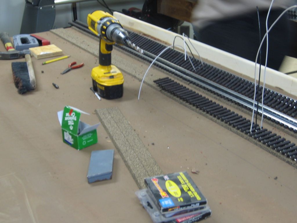
so as I am thinking about laying track on my new layout, I know I want to run both TMCC and DCS. I am usin Gargraves flex track in 3 foot or so sections.  I was thinking I might pre wire each section in about the middle of the piece with pigtail leads to the middle and one side rail as I lay the track. Feed those pigtails through holes underneath the track for later wiring into the power grid.  I was also considering scolding a connection between the 2side rails on each pice to ensure the two side rails are electrically the same.  

Bad idea to pre-wire the sections this way? Would it be better to just do the wiring to each section after the track is in place?

my first hi-rail layout so I need your advice.  


Don Merz

Original Post

Replies sorted oldest to newest

The other thing you can do is use the GarGraves pigtails.  These are essentially track pins with leads soldered to them.

http://www.gargraves.com/accessories.html#pwires

If you don't know how to solder or prefer not to, these are very useful.  A bit pricey, but useful.

I believe these are 16 gauge wire (don't quote me).  Anyway, I will also be using 12 gauge stranded wire for my buses - actually Red / Black zipcord.

George


gunrunnerjohn posted:

I'm not a fan of the pigtails, Atlas has them as well.  You're just adding a frequently poor connection between you and the track for no reason.  Soldering the wire to the track is a far superior method, at least IMO.

It may well be a superior method but I haven’t soldered since 8th grade shop class.  In the process of laying and wiring track, I will be testing every connection.

George

Don:

If I am not mistaken I believe Gargraves is a tubular style with a slot running along the bottom. If this is the right track style then I have seen some simply solder wire to a thin piece of metal that fits snugly into the track slot. You can even solder the connection if you want. This is a little more involved than simply soldering wire to track but the thing I like about this process is that you can make up a whole bunch of these connectors at your bench and then bring them to the layout, attach to the track wherever you want and drop into a hole in the base.

I also (like John and Mike do) run three wires whether I want to use one ground track for an accessory or simply to make sure I have a solid ground.

Joe

I prefer soldered rail feeder connections, because they are more dependable than the alternatives. A thin tab slipped into the slot in the bottom of a rail may provide an adequate electrical connection at first, but over time it is subject to corrosion and to movement with resulting loss of good contact. On my 2-rail layout I soldered an 18-gauge solid feeder to every individual piece of rail and I have never had a problem with continuity. I made the feeders as short as possible between the rail and the 10-gauge stranded buss, to which they are also soldered. Soldering drop wires/feeders to the rails isn't very difficult if you use a good iron and the correct flux and practice for awhile with an old piece of track, and it is definitely worth the trouble, in my opinion.

Personally, I would not connect the outside rails together with a separate "bridge" wire. Just provide all three leads, then if you want them connected, you can do it below the deck. For my mainlines, I only use one rail for ground. The other one is for detection, as GRJ pointed out.

I don't solder my feeders, too much work. I use the crimp tab connectors, they make that center rail easy. I use a combination drill/countersink bit to go through the roadbed. This provides a large enough hole for the wire, as well as relief for the shoulder of the connector. It also makes it nearly impossible to pull them out.

Stranded wire is a must. I like 16 gauge, and I put feeders on every 3' section. Short pieces don't get them. I try not to rely on pins for electrical connections. They really should be for track alignment only.

Add Reply

Post
×
×
×
×
Link copied to your clipboard.
×
×