Hell all. I am about to start planning and building my Hi-Rail Scale  layout using Gargraves Track and ultimately Ross

Custom Switches. I have purchased Gargraves Sectional Curved track in 120" , 128" and 138" Diameters, with a view to building a Triple Track Main Line for much of my available 29' x 18' layout space. I also purchased 80 sections of Gargraves 37" Flex Track. I have been reading the posts re Track Centre Spacing of 6" being the ideal spacing standard. I have a Big Boy, Allegheny, B&O Em-1, and other Articulated Locomotives, as well as 21" Passenger Cars.

Am I in strife as far as track centre spacing goes with the 120", 128", and 138" curved Track.   I live in Orange,  NSW  Australia, and there aren't any Hi-Rail enthusiasts around here for me to discuss these issues with.  ( We do have a very  good Live Steamers Club in town though).

Any advice greatly appreciated.

regards,

Alan Ford

Original Post

Replies sorted oldest to newest

Alan Ford posted:

... I have been reading the posts re Track Centre Spacing of 6" being the ideal spacing standard. I have a Big Boy, Allegheny, B&O Em-1, and other Articulated Locomotives, as well as 21" Passenger Cars ...

Alan Ford

6" track centres will certainly provide clearance on curves, but it compromises appearance and realism to have tracks that far apart. I suggest you set up a test oval with your O-120 curves and measure the maximum overhang of your longest cars and locos, both inside and outside the curve. Set up blocks along the track so the car or loco just clears while moving past, and measure from the edge of the block to the track centerline. Then you will have good numbers for your specific conditions: add the maximum inside and outside clearances plus a safe margin of about half an inch. Tracks will look better if you can transition to closer spacing on straight sections IMO.

The easiest way to use your fixed-radius track sections for reasonably concentric triple-track curves is to make curves of 90-degrees or less, and average the track spacing as best you can.

Last edited by Ace

Alan,

The "natural" spacing for the center rails based on the diameters of those tracks are 5" between the 138 and 128 and 4" between the 128 and 120.

The NMRA still has 4.5" as their standard for O (1:48) scale.

That's a little close with 21" passenger cars and an articulated steamer, but, they will clear on this large diameter track.

The other oddity is that you only have 25° of arc with the sectional track in the large radius.

Keeping 4" on the straights will look great, but you will need to use easement tracks to get into and out of the 138 and 128 curves to keep them at 5". The 120 will set up naturally off of 4" straight spacing.

All of that being stated, 5.5" and 6" center rail spacing has been used on concentric curves in most of the large layout builds I've looked at in recent times.

This will also help in fitting the turnouts. 4.5" centers or less makes the turnout placement critical.

I think you'll find that you have an interesting build, setting 5.5" centers in the curves and 4" straights.

SCARM is nice layout design freeware, but is currently missing an easement tool. use the "official"link at the top of the page in bold blue letters.

I know that we have a serious time difference, but, if you get a working track plan with your center rail spacing for straights, I can create the easement tracks in RR-Track and give you the offset points to get to the curve centers that you want.

Last edited by Moonman

Allan, you should be in pretty good shape with curves that large. I think the 6-inch "standard" was for big locos and cars on curves in the O72 - O80 range.

I have no direct experience working with GarGraves track and would be interested to know how "flexible" are the fixed-radius and straight pieces? Perhaps you can spring an extra inch on the radius when it is fastened down. Flex-track will be useful in some places. Moonman has made you a generous offer to engineer the details!

Moonman posted:

Alan,

The "natural" spacing for the center rails based on the diameters of those tracks are 5" between the 138 and 128 and 4" between the 128 and 120.

The NMRA still has 4.5" as their standard for O (1:48) scale.

That's a little close with 21" passenger cars and an articulated steamer, but, they will clear on this large diameter track.

The other oddity is that you only have 25° of arc with the sectional track in the large radius.

Keeping 4" on the straights will look great, but you will need to use easement tracks to get into and out of the 138 and 128 curves to keep them at 5". The 120 will set up naturally off of 4" straight spacing.

All of that being stated, 5.5" and 6" center rail spacing has been used on concentric curves in most of the large layout builds I've looked at in recent times.

This will also help in fitting the turnouts. 4.5" centers or less makes the turnout placement critical.

I think you'll find that you have an interesting build, setting 5.5" centers in the curves and 4" straights.

SCARM is nice layout design freeware, but is currently missing an easement tool. use the "official"link at the top of the page in bold blue letters.

I know that we have a serious time difference, but, if you get a working track plan with your center rail spacing for straights, I can create the easement tracks in RR-Track and give you the offset points to get to the curve centers that you want.

Thanks for your offer Re  RR-Track for the Easement calculations Carl. I will get a Track Plan done of my envisaged Main Lines and email it to you on the Forum. BTW I checked my Gargraves Catalogue, and the 120" diameter curved sections  have a 30 deg arc (12 sections to a circle), while the 128" and 138" diameter sections have   a 22.5 deg arc (16 sections to a circle) so no problem for a 90 deg bend on the main line. I plan to use Ross #6 or #8  Turnouts for Main Line crossovers. I thought of inserting a short section of straight rail in the diverging route through any mainline crossovers, to  increase track centre separation to match the sectional curves, but that may possibly entail  more work than constructing a  few easement curves.

Regards

Alan Ford

Ace posted:

Allan, you should be in pretty good shape with curves that large. I think the 6-inch "standard" was for big locos and cars on curves in the O72 - O80 range.

I have no direct experience working with GarGraves track and would be interested to know how "flexible" are the fixed-radius and straight pieces? Perhaps you can spring an extra inch on the radius when it is fastened down. Flex-track will be useful in some places. Moonman has made you a generous offer to engineer the details!

Thanks for the advice Ace,  I will forward my Track Plan to Moonman  on completion.

regards,

Alan Ford

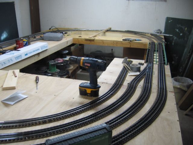
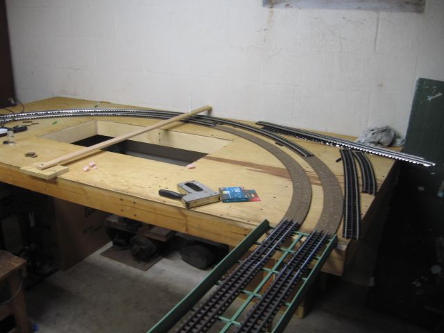
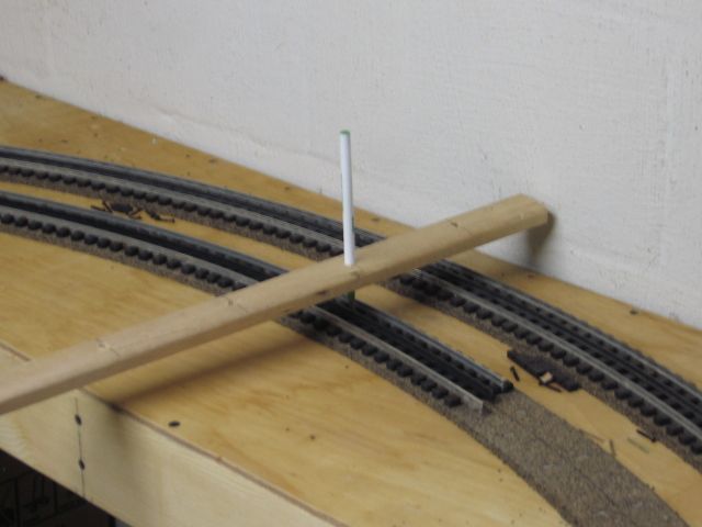
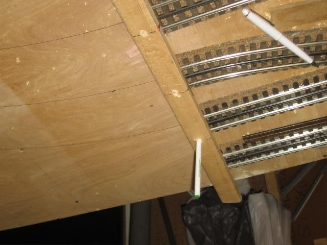
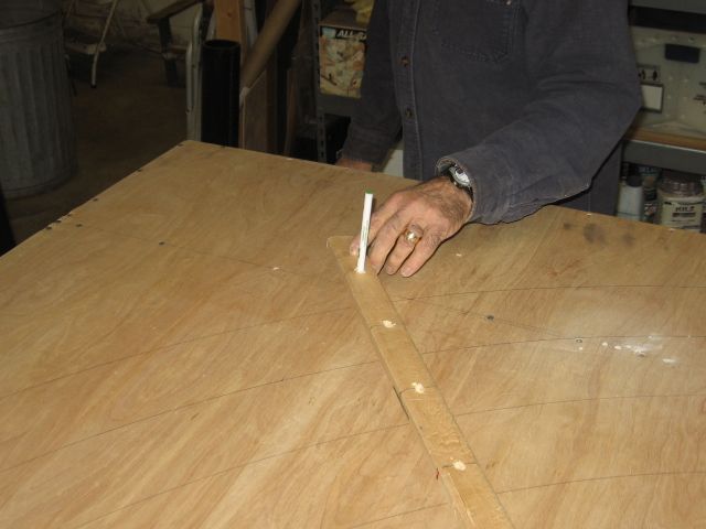
This was assembled using 4.5" center to center spacings.  Second hand/used Gargraves flex track.

The idea is to keep the ball point pen on the center rail as the track is secured to the deck through the cork road bed.

Screws are installed every 4" to 5". Ties are spaced evenly and the end of the piece is cut, (inside long rails are cut short), with a dremel before the next piece is started. 

Last edited by Mike CT
Alan Ford posted:
Moonman posted:

Alan,

The "natural" spacing for the center rails based on the diameters of those tracks are 5" between the 138 and 128 and 4" between the 128 and 120.

The NMRA still has 4.5" as their standard for O (1:48) scale.

That's a little close with 21" passenger cars and an articulated steamer, but, they will clear on this large diameter track.

The other oddity is that you only have 25° of arc with the sectional track in the large radius.

Keeping 4" on the straights will look great, but you will need to use easement tracks to get into and out of the 138 and 128 curves to keep them at 5". The 120 will set up naturally off of 4" straight spacing.

All of that being stated, 5.5" and 6" center rail spacing has been used on concentric curves in most of the large layout builds I've looked at in recent times.

This will also help in fitting the turnouts. 4.5" centers or less makes the turnout placement critical.

I think you'll find that you have an interesting build, setting 5.5" centers in the curves and 4" straights.

SCARM is nice layout design freeware, but is currently missing an easement tool. use the "official"link at the top of the page in bold blue letters.

I know that we have a serious time difference, but, if you get a working track plan with your center rail spacing for straights, I can create the easement tracks in RR-Track and give you the offset points to get to the curve centers that you want.

Thanks for your offer Re  RR-Track for the Easement calculations Carl. I will get a Track Plan done of my envisaged Main Lines and email it to you on the Forum. BTW I checked my Gargraves Catalogue, and the 120" diameter curved sections  have a 30 deg arc (12 sections to a circle), while the 128" and 138" diameter sections have   a 22.5 deg arc (16 sections to a circle) so no problem for a 90 deg bend on the main line. I plan to use Ross #6 or #8  Turnouts for Main Line crossovers. I thought of inserting a short section of straight rail in the diverging route through any mainline crossovers, to  increase track centre separation to match the sectional curves, but that may possibly entail  more work than constructing a  few easement curves.

Regards

Alan Ford

Alan,

Thanks for pointing out the obvious error in the SCARM library. I will contact the author of the software and have him correct the length of the O113 - O138 to 22.5° curves.

That will make things a little easier.

I just tested crossovers spacers for the Ross switches. I tried the Ross #010 3" straight. It doesn't set the centers on the spacing we have discussed. Gargraves is not that tough to cut for the spacers.

Keep in mind the length of #6 and #8 turnouts.

OK,

I used the Ross double#8 crossover to set 4" spacing into curves and created 21"L x 2-5/8"W rectangles to set on the curves. You can see that they will contact.(done in SCARM) I would try 4" mains into 5" centers on the curves. You can do this with only a few curve sections and two of your cars.

The 4" mains with easements to 5" centers on the curves looks like photo #2 done in RRT. I have to work on the 120" easement as there is no auto calculator for that radius track. The O138 and the O128 look good. I have the numbers for all saved.

Attachments

Images (3)
  • Alan_Ford_21_inch_car_clearance
  • Alan_Ford_4_Mains_to_5_centers_on_curves
  • Alan_Ford_4_Mains_to_5_centers_on_curves_track_view
Last edited by Moonman
Moonman posted:
Alan Ford posted:

... BTW I checked my Gargraves Catalogue, and the 120" diameter curved sections  have a 30 deg arc (12 sections to a circle), while the 128" and 138" diameter sections have   a 22.5 deg arc (16 sections to a circle) ...

Alan Ford

Alan,

Thanks for pointing out the obvious error in the SCARM library. I will contact the author of the software and have him correct the length of the O113 - O138 to 22.5° curves ... 

I thought it was odd that some wide-radius pieces were a 25-degree arc. I've corrected these wide-radius pieces with text editing in the attached SCARM file, according to the specs on the GarGraves web site. You can just copy and paste and re-copy them into another SCARM file. Hopefully Mixy will correct the GarGraves items in the SCARM library some time.

GarGraves wide curves corrected-a

Note that there are some spec differences between wood and plastic tie versions.

Attachments

Last edited by Ace
Mike CT posted:

This was assembled using 4.5" center to center spacings.  Second hand/used Gargraves flex track.

The idea is to keep the ball point pen on the center rail as the track is secured to the deck through the cork road bed.

Screws are installed every 4" to 5". Ties are spaced evenly and the end of the piece is cut, (inside long rails are cut short), with a dremel before the next piece is started. 

Thanks for the photo's and advice Mike, good construction method. As the saying goes, a picture tells a thousand words.

regards,

Alan Ford

Oman posted:

I believe 4.5" spacing is ideal. I'm building with Atlas and their track is 4.5" spacing on ALL track, not just some.

Yes, 4.5" spacing is pretty good appearance-wise and that is my preference, but some guys want to run the largest articulateds and scale-length passenger cars on O72 - O80.

Ace posted:
Oman posted:

I believe 4.5" spacing is ideal. I'm building with Atlas and their track is 4.5" spacing on ALL track, not just some.

Yes, 4.5" spacing is pretty good appearance-wise and that is my preference, but some guys want to run the largest articulateds and scale-length passenger cars on O72 - O80.

Absolutely true. I had two large duplex engines, but I didn't like how 1 pair of drivers were barely on the rails as they navigated O-81. So, I sold them. I'll stick to locomotives that are more suited to my curves (O-72 minimum). My passenger cars are 18".

Alan,

I also used 4-1/2" track spacing and have not had any issues running my Big Boys (MTH Premier and Lionel VL). Only problem I had was if I tried running a Big Boy on the inner main and the MTH Premier DDA40X on the outer main - the DDA40X protrudes a lot into the inside of a curve. My mains are Ø108" and Ø99" as these were the largest sectional curves Atlas had at the time, five years ago. Other curves I used were Ø90" and a few Ø81".

As Mike mentioned above, and even though I used sectional curved tracks, using a 'compass' is key. Sometimes the center of the compass falls in empty space, so you have to improvise. Here are but a few examples from my construction in April 2011:

B Center South Tracks DSCN0516C Center South East DSCN0511D Center Four Tracks DSC03580

I also found that home-made track spacing gauges were VERY helpful in keeping everything properly aligned.

Track Gauges -3- med crp DSC03522

Good luck!

Alex

Attachments

Images (4)
  • B Center South Tracks DSCN0516
  • C Center South East DSCN0511
  • D Center Four Tracks DSC03580
  • Track Gauges -3- med crp DSC03522
Last edited by Ingeniero No1
Mike CT posted:

This was assembled using 4.5" center to center spacings.  Second hand/used Gargraves flex track.

The idea is to keep the ball point pen on the center rail as the track is secured to the deck through the cork road bed.

Screws are installed every 4" to 5". Ties are spaced evenly and the end of the piece is cut, (inside long rails are cut short), with a dremel before the next piece is started. 

Mike

Thanks for sharing your photos and technique.

What size curves are these?

What size locomotives and passenger cars are you able to run?

Bob

Ingeniero No1 posted:

Alan,

I also used 4-1/2" track spacing and have not had any issues running my Big Boys (MTH Premier and Lionel VL). Only problem I had was if I tried running a Big Boy on the inner main and the MTH Premier DDA40X on the outer main - the DDA40X protrudes a lot into the inside of a curve. My mains are Ø108" and Ø99" as these were the largest sectional curves Atlas had at the time, five years ago. Other curves I used were Ø90" and a few Ø81".

As Mike mentioned above, and even though I used sectional curved tracks, using a 'compass' is key. Sometimes the center of the compass falls in empty space, so you have to improvise. Here are but a few examples from my construction in April 2011:

B Center South Tracks DSCN0516C Center South East DSCN0511D Center Four Tracks DSC03580

I also found that home-made track spacing gauges were VERY helpful in keeping everything properly aligned.

Track Gauges -3- med crp DSC03522

Good luck!

Alex

Thanks for the good information Alex, in particular re the home made track spacing gauges and the compass.

regards,

Alan Ford

RRDOC posted:
Mike CT posted:

This was assembled using 4.5" center to center spacings.  Second hand/used Gargraves flex track.

The idea is to keep the ball point pen on the center rail as the track is secured to the deck through the cork road bed.

Screws are installed every 4" to 5". Ties are spaced evenly and the end of the piece is cut, (inside long rails are cut short), with a dremel before the next piece is started. 

Mike

Thanks for sharing your photos and technique.  You're welcome.

What size curves are these?  O 88, O 81, O 74, O 67,  The two plywood tables would be 96" wide.

What size locomotives and passenger cars are you able to run?  Most all that would run O 54 and larger.

Bob


Add Reply

Post
The Track Planning and Layout Design Forum is sponsored by

AN OGR FORUM CHARTER SPONSOR
×
×
×
×
Link copied to your clipboard.
×
×