Originally Posted by train1872h:

I have a question, have the LED rolls, how do I wire them for DC.  so the lights won't go out when I change direction.

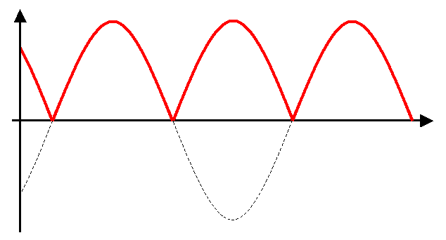
As GRJ says, a bridge rectifier solves the direction change problem.  However for conventional DC operation, I'd wonder if there's enough track voltage at slower speeds to drive a 12V DC LED roll. Lower voltage operation is discussed in the 300 LED Rope thread though focused on AC operation so some techniques won't apply to you.  You might want to start a separate DC thread.

The choke prevents the current-regulating circuit from degrading a DCS signal.


While the Superliners I'm working on will be run conventionally at first (I'm pulling the train with a pair of Williams Genesis units, seeing that they're the only easily available ones in the current Amtrak scheme), I'll eventually upgrade them to command operation in a mixed TMCC/DCS environment. Adding the choke now means I won't have to reopen the cars and add it later once the locos are upgraded (however long that takes), and it won't hurt conventional operation in the meantime.


---PCJ

Originally Posted by RJR:

Thanks RR & GRJ.  I know the purpose of a choke, but was wondering if this circuit has been causing problems without a choke.

Lighted passenger cars with constant intensity lights have been known to cause issues with DCS.  This is just cheap insurance that there will be no problem.  The thing is, the problem is cumulative, so as you add offending circuits, the DCS signal gets weaker.  So, you don't necessarily know if you're screwing it up until it gets bad.


Depends on the current, the size of the cap, and the capacity of the transformer.  If you have a really huge cap, and a really powerful transformer, even drawing power from the load, the output voltage would be very close to the peak voltage of the rectified output.


The problem with using unregulated supplies is you can't be certain what voltage you'll get under varying input voltage conditions.


A one foot length of the LED's would probably be 18 of the LED's if these are the 300 LED 5 meter strips.  This number would require 120ma to light at full intensity.  The easy way to do this task is use the LM317T regulator in a constant current configuration to supply 120ma to the strip.  You'll get full intensity and the voltage input won't affect the supply current.  You need about a volt and a half of headroom from the input of the regulator to the output.


Truthfully, that strip running at full intensity is going to be pretty bright, I rarely run LED's at full current in modeling applications.

And, I use the term correctly.   The LM317 can be wired in a constant current configuration, and it's perfect for this kind of application.  Note the resistor value sets the current, pick your poison.  I've included the configuration below, and if you visit the LM317 Current Calculator you can quickly compute the resistor you need for any desired current.


Constant Current LED Driver Filtered with LM317

Attachments

Images (1)
  • Constant Current LED Driver Filtered with LM317

Thanks, GRJ, that link is excellent.  The schematic you included in the just-above post is the same as you posted a few days ago, but with a diode vice a full-wave bridge.  Correct.


Now let me ponder a moment.  If the 317 were to be set up as a voltage regulator rather than a current regulator, then it could be set so it didn't matter how many LEDs you have in a circuit.  Correct?  This would permit one to assemble & put on the shelf a bunch of them for use with any application using these 12-volt strings, regardless of length. 

GGG:  The link GRJ sent to the current calculator is to a British web site that contains interesting discussions of the LM317.  You can set it up to provide constant max current regardless of load or voltage, or as constant max voltage regardless of current.  All within its capabilities, of course.

Originally Posted by RJR:

GGG:  The link GRJ sent to the current calculator is to a British web site that contains interesting discussions of the LM317.  You can set it up to provide constant max current regardless of load or voltage, or as constant max voltage regardless of current.  All within its capabilities, of course.

RJR,  Thank you.  I was just trying to clarify that you can't put an unlimited number of LEDs in series with a 12V source.  Each LED will drop 2-3V depending on the spec.  Same for current.  If each individual 3 LED segment is using 10ma, and you have 6 segments in the passenger car, then the regulator is seeing a 60ma load.  G

I fabricated a few of the voltage regulators.  Photos are attached.  After finishing the first, I added a 470mfd capacitor; the second I built with ojne.  Unfortunately, it is not adequate to compensate for the lousy Williams rollers losing contact with the track.  I used 2 strips in the one car I've finished.  The LEDs I got were the cool white, which has a blueish cast I don't care for.  I've ordered some warm white.

20130623_164738

20130623_164813

Attachments

Images (2)
  • 20130623_164738
  • 20130623_164813

Stan:  The LEDs don't fade out; they just go on & off.  The 470mfd cap made no difference in this.  Checking the Williams car that was the first installation, I find that it has a lousy ground.  If I connect my ohmmeter between wheels on each of the 2 trucks, there is spotty contact.  The Williams trucks don't have a pick up finger to the axles, and a loose connectioon to the car frame.  I'll have to study this more.


Sublinked to a link gunrunnerjohn had posted, is a info sheet on resistor sizes for various voltages:

http://www.reuk.co.uk/LM317-Voltage-Calculator.htm


I used the schematic (below) on the first page of that link, and per the table later on in the link, selected 470 ohms (R1) and 3300 ohms (R2) to yield 10.03 volts.  Can't vouch for the colors as they appear on the screen, but the R-S packs said 33k.


Schematic:


lm317t-voltage-regulation-circuit

Attachments

Images (1)
  • lm317t-voltage-regulation-circuit
Last edited by RJR

I don't mess around using analog regulators as Buck Converters are much more efficient.

http://www.ebay.com/itm/1pcs-LM2596S-Power-Module-DC-DC-Buck-Converter-Step-Down-Module-LM2596-/121129615011?pt=LH_DefaultDomain_0&hash=item1c33e33ea3

Infact been kicking around the idea of mounting the Buck in a baggage car and then tying all the cars together with mini 2 pin plugs. Also in the baggage car will be a LiOn battery powering all the lights. Then can remove all the power pickup rollers to get rid of the drag. We do this in the large scale world and it works great along with using ball bearings in the journal boxes.  


Stan, yes 3300 ohms.  I checked with voltmeter and got 10.1 volts.  Given the tolerance of resistors and the unit, that's close enough to the 10.03 volts the table shows for those resistors.

Grj:  not 12 volts.


Am working on a Williams observation car & found it has grain-of -wheat incandescent bulbs in marker lanterns, both burned out.  Had a few gow bulbs on shelf, so am also feeding them from the regulated 10.1 volt supply for led's.  Now will tackle improving ground feed from wheels.

Post
The DCS Forum is sponsored by

OGR Publishing, Inc., 1310 Eastside Centre Ct, Ste 6, Mountain Home, AR 72653
800-980-OGRR (6477)
www.ogaugerr.com

×
×
×
×
Link copied to your clipboard.
×
×