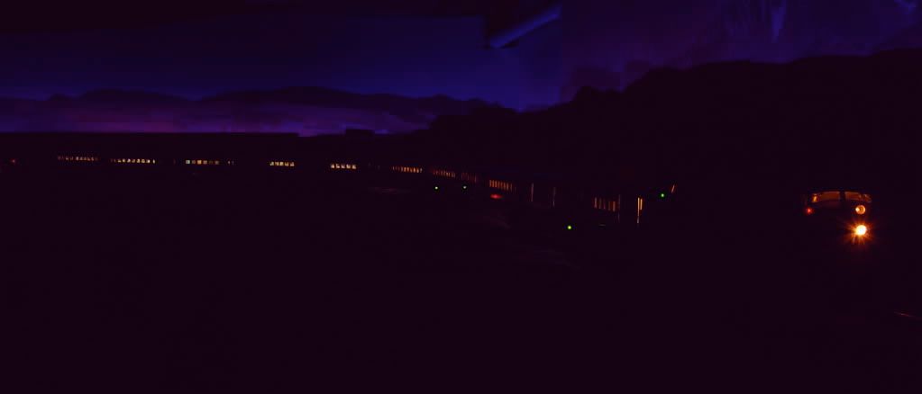
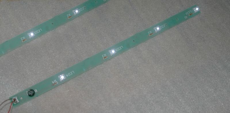
Finally managed to exceed the ability of our Z4000 to put out enough amps to pull 12 lighted full-length passenger cars around an "S" reversing loop with two powered Atlas F units.   Just as it got to full pull .... zap!  The lights went out.


Time to look at those LED setups for passenger cars GGD passenger cars.

Original Post

Replies sorted oldest to newest

And this is why I propose that you alternate blocks into power channels.

Using Blocks also helps DCS signal but splitting the consist across both handles gives you more watts to run with. A 12 car consist should be much longer than the block, moving some cars to the other handle for it's 180 Watts.


By quick math, 21" cars take roughly 2 sections of track each, so blocks of 12 pieces of track gives you the cars split evenly over 2 blocks. This puts the engines back on the handle with the aft 6 cars but splits the power fairly well.

The trackage is basically divided into 4 power districts.  The trains are usually under 25' so they will be in a district, as well as overlap when going from one to another.
 
This section of trackage is an "s" curve which is in one block.
 
I'll look into breaking that section into two blocks.
 
As well as looking into what it would take to convert these GGD cars to LED ...
 
Originally Posted by Russell:

And this is why I propose that you alternate blocks into power channels.

Using Blocks also helps DCS signal but splitting the consist across both handles gives you more watts to run with. A 12 car consist should be much longer than the block, moving some cars to the other handle for it's 180 Watts.


By quick math, 21" cars take roughly 2 sections of track each, so blocks of 12 pieces of track gives you the cars split evenly over 2 blocks. This puts the engines back on the handle with the aft 6 cars but splits the power fairly well.

This is interesting...  I have run a 3 engine set (two powered) and pulling 12 lighted cars plus two head end cars on one hanlde of a ZW and it handled it all fine.  This on an oval where the distance between the obs car and lead unit was only 18".  I suppose the S curve makes the difference?

It's a pretty tight "s" curve with 72* curves more or less.  The drag on those big cars is quite a bit.
 
Makes me wonder: is the 10amp limit on the entire Z4000 or is it a limit on each handle with the total transformer capacity being 20amps?
 
Originally Posted by Charly:

This is interesting...  I have run a 3 engine set (two powered) and pulling 12 lighted cars plus two head end cars on one hanlde of a ZW and it handled it all fine.  This on an oval where the distance between the obs car and lead unit was only 18".  I suppose the S curve makes the difference?

Hi Kerrigan,


Welcome to the wonderful world of LED passenger car lighting.  We converted all the rolling stock on the NWTL a few years ago for exactly the same reason.  Once you convert the passenger cars to LED's you car run equal length freight and passenger trains with roughly the same amperage draw.


We converted this 11-car K-Line GN Empire Builder set with lighting boards from Jack Pearce.  Before conversion the passenger cars alone drew 5.5amps.  After conversion they drew 20mA.  Yep, less than 2mA per car!


That looks very cool!
Is there a website for these lights?
 
Originally Posted by Dave Hikel:

Hi Kerrigan,


Welcome to the wonderful world of LED passenger car lighting.  We converted all the rolling stock on the NWTL a few years ago for exactly the same reason.  Once you convert the passenger cars to LED's you car run equal length freight and passenger trains with roughly the same amperage draw.


We converted this 11-car K-Line GN Empire Builder set with lighting boards from Jack Pearce.  Before conversion the passenger cars alone drew 5.5amps.  After conversion they drew 20mA.  Yep, less than 2mA per car!


Originally Posted by Kerrigan:
 
That looks very cool!
Is there a website for these lights?

 Unfortunately, no.  Jack has a nice retirement business doing what he enjoys and isn't interested in growing the business.  He goes to York and sells to anyone who contacts him at home.  Here's his e-mail address if you'd like to contact him:


jack_pearce4@sympatico.ca


I highly recommend Jack's warm white LED boards for folks running command control.  They have an excellent color LED (which Jack let me pick when he was making a production run), they are easy to mount in the cars (especially in MTH passenger cars), they have capacitors for flicker free lighting, you can adjust the lighting level by changing a single resistor, they provide an extra circuit for marker, drumhead, and other lights, and they do not interfere with the DCS signal.  There are cheaper ways to convert to LED's, but if you value your time Jack's boards are hard to beat.

If you want to DYI here is how I do it for command. Cost about $2 per car or less. Draw is 20 ma per car for maximum brightness. At 18 volts that is about 1/3 watt per car. Reducing brightness with larger resistor size will lessen current draw.


 http://www.jcstudiosinc.com/Bl...=407&categoryId=


See also caboose lighting for better pictures


http://www.jcstudiosinc.com/Bl...=487&categoryId=


Dale H

And, if you're lazy like me, you can use the LED strip rolls.


Here's a 5 meter roll of self-adhesive LED's for $6.99 shipped:


5M 500CM Warm White 3528 SMD LED Strip Lights 300 leds


Add a couple of components and you have even lighting throughout the car.  Figure an 18" car, you can easily get 10 cars from one strip, so that's less than a dollar a car.  Add a diode, resistor, and a capacitor, and you are in for around $2 and very little labor.  If you want to get fancy and spend another 50 cents, you can use a constant current source to have constant intensity lighting.

Originally Posted by Dave Hikel:

Hi Kerrigan,


We converted this 11-car K-Line GN Empire Builder set with lighting boards from Jack Pearce.  Before conversion the passenger cars alone drew 5.5amps.  After conversion they drew 20mA.  Yep, less than 2mA per car!


Dave,  2ma each car?  Doesn't seem reasonable to be that low.  LED run around 10-20ma, and even if a resistor was installed to limit the current, getting a string of LEDs in a car to run on just 2ma seems amazing.  G

GGG


This was discussed a while ago on the Forum. Jack does fine work ,however his boards are not constant voltage lighting desired by conventional operators. 20 ma LEDs can be dimmed down to a point by simply using larger resistors than the minimum value needed to protect it. Current draw will reduce also.


The big criticism of LEDs when they originally came out were that


1, they were too dim


2 They were directional points of light


3 They put out an unrealistic bluish cast.


Many modern LEDs do not have these problems. The LEDs I use are as bright as original light bulbs. View angle is 140 degrees similar to  a light bulb with a reflector. The warm white ones put out a spectrum close to that of an incandescent bulb.


I am a toy train guy who runs conventional so I make my LEDs bright and run them at 20 ma with a CV circuit. Mine use a bit over 1 watt per car. A command circuit at full brightness would use about 1/3 watt per car. However they can be dimmed as described and would pull less current for those desiring that. The current pull really is a non issue when using LEDs. Even with a CV circuit an 8 car set pulls about 8 watts. If it pulled only 1/2 watt it is not a big deal. Passenger cars sets with bulbs could pull almost 100 watts depending on model.


Jack does fine work and I am not knocking it at all. The advantage of DYI is that you can make them the way you want, make custom shapes and they are much cheaper. See the caboose circuit I linked earlier if interested.


The hardest part for me is getting the #$%^& car apart. After you do a few you can convert a set in an evening.


Here is a link to a long discussion on Jack's boards. He does not provide a schematic or parts used. However there is a lot of information on different approaches by people doing it themselves.


https://ogrforum.com/t...er-car-lighting-kits


Dale H


You adjust the brightness by controlling the current to the LED's.  That's what we've been discussing here.  Here's a simple circuit for each car that does the job with about $1.50 in components.


For instance, if you use a 2500 ohm resistor in this circuit, you'll get 1/2 a milli-amp and get pretty dim lighting.  You can bring that value down until the LED's are as bright as you like.


If you are running strictly command, you can also just use a diode and a resistor for really simple installation.  A capacitor will add flicker suppression if desired.


LED's are really easy to work with, and very flexible.


Constant Current using 3-terminal regulator

Attachments

Images (1)
  • Constant Current using 3-terminal regulator

If you're adjusting the current in the LEDs, then one must be careful not to exceed the LEDs' rating, I assume.  Looking at the circuit, I would think that raisng the .1uf capacitor to a very large size would eliminate the flicker so common on model railroad car lighting.  (My passengers are complaining of headaches & blindness.)


What source did you use for the bridge rectifier & the LM317LZ?

Last edited by RJR

Yep, the .1 is there just to keep the regulator from possible oscillation, but it can be a larger value to reduce or eliminate flicker.  Obviously, you have to limit the current to the LED max rating, but that's not really an issue, since running those strips at their maximum current rating looks like you have a fusion reaction going in the passenger cars!


Another consideration is using the LM317T if you draw much current, as the small TO-92 package doesn't dissipate much power.

I just ordered two strips.  Went thru Amazon rather than the HongKong supplier you referenced, since if there's a problem Amazon is easy to work with.  I'm planning on doing 10 passenger cars, plus station platforms where the cheap 18-volt bulbs I bought in bulk burn out rather regularly.


For the passenger car lighting, GRJ, what resistance do you use for the control?  IN the schematic you used, please verify that the OUT & ADJ terminals are as shown.


For the station lighting power supply, I'm thinking of using the 10-volt output of the Z4000.  I doubt there is any need for the LM317LZ in such a configuration.  Do you agree?

Originally Posted by Kerrigan:

I thought about going with LEDs in the GGD Heavyweights until someone mentioned they are very difficult to take apart and get back together correctly.


That scared me off ... too much tied up in the cars to mess them up.

GGD site shows an LED conversion kit which suggests it ought to be practical.  I'd think they have provisions to change the original incandescent bulbs should they burn out so another idea would be to see if there's a plug-in compatible LED replacement. 


From their website:


Originally Posted by stan2004:
Originally Posted by Kerrigan:

I thought about going with LEDs in the GGD Heavyweights until someone mentioned they are very difficult to take apart and get back together correctly.


That scared me off ... too much tied up in the cars to mess them up.

GGD site shows an LED conversion kit which suggests it ought to be practical.  I'd think they have provisions to change the original incandescent bulbs should they burn out so another idea would be to see if there's a plug-in compatible LED replacement. 


From their website:


Several shortfalls of the GGD boards as I remember. Correct me if I am wrong.


No capacitor for flicker free lighting.LEDs are more prone to flicker than light bulbs without a capacitor.


They are not constant voltage for conventional operators.


They are wired in parallel and use more amperage than if wired in seroies.


Dale H

Originally Posted by RJR:

I just ordered two strips.  Went thru Amazon rather than the HongKong supplier you referenced, since if there's a problem Amazon is easy to work with.  I'm planning on doing 10 passenger cars, plus station platforms where the cheap 18-volt bulbs I bought in bulk burn out rather regularly.


For the passenger car lighting, GRJ, what resistance do you use for the control?  IN the schematic you used, please verify that the OUT & ADJ terminals are as shown.


For the station lighting power supply, I'm thinking of using the 10-volt output of the Z4000.  I doubt there is any need for the LM317LZ in such a configuration.  Do you agree?

For constant current, the schematic is indeed correct, you can simply Google LM317 Constant Current and find many examples.  The actual resistance used depends on how bright you want the lights, that's the beauty of the circuit.  You can go from moonlight to bright sunlight in the cars.


As far as the 10V output, remember when you add rectifiers and diodes at low currents, you'll have a lot more than 10VDC, so I suggest you not try to do this without at least a resistor to limit current.

Thank you; I had not seen that ad ...
 
Originally Posted by stan2004:
Originally Posted by Kerrigan:

I thought about going with LEDs in the GGD Heavyweights until someone mentioned they are very difficult to take apart and get back together correctly.


That scared me off ... too much tied up in the cars to mess them up.

GGD site shows an LED conversion kit which suggests it ought to be practical.  I'd think they have provisions to change the original incandescent bulbs should they burn out so another idea would be to see if there's a plug-in compatible LED replacement. 


From their website:


Originally Posted by RJR:

You're saying that the rectifiers and diodes [and capacitor] will increase the DC output to approximately the peak voltage of the AC sine wave?  Interesting.


To avoid having to by a selection of resistors is why I asked you what value you used in your passenger cars.

I supplied the whole 18" strip about with 20ma, I used a 68 ohm resistor. 

Originally Posted by train1872h:

I have a question, have the LED rolls, how do I wire them for DC.  so the lights won't go out when I change direction.  Thanks in advance

I see the DC running wasn't really mentioned, but with the bridge rectifier as pictured, either polarity of DC will still act to light the LED's.  Oh, and if you don't want to struggle with the surface mount resistor, you can just use a standard 1/4w axial lead resistor in that spot.  You adjust the resistor value for the brightness desired.

Post
The DCS Forum is sponsored by

OGR Publishing, Inc., 1310 Eastside Centre Ct, Ste 6, Mountain Home, AR 72653
800-980-OGRR (6477)
www.ogaugerr.com

×
×
×
×
Link copied to your clipboard.
×
×