I have a 3 rail layout and I'm having trouble with one of my Ross switches with the 1000 switch machine. I have wired this switch for non derailing and when I check the voltage on the isolated rails I get 28 volts on one and 37 on the the other. I disabled non derailing on this switch for now until I figure this out. I also have 2 other Ross switches with 2500 machines with non derailing and the voltages are fine on those. 

I have a PH180 powering the track and a MTH 1000 powering the switch motors. They are grounded together.  I have both transformers plugged into the same power strip. 

Original Post

Replies sorted oldest to newest

Tanner:

Another possibility - when you connected the non-derail wires somehow you got the two power supplies in series with each other so the voltage is adding. Easy enough to check. Turn one transformer off and leave the other on. Check voltage. Then switch transformers on/off and check again. If you get voltage both ways the transformers are somehow connected together.

The two transformers can share the same ground and power strip but I don't think they need be in phase with each other because if I understand what you did, one transformer powers track and the other powers the switch motors so their power wires should be on separate circuits independent of each other. Maybe for the isolated track you crossed power wires accidentally or connected a ground wire to a power line connecting one transformer to the other?

Please let us know what happens

Joe

I agree it acts like a phasing issue but as romiller said I can't just reverse one plug. the only thing I can think of doing is opening the MTH and reversing the internal connections.  Should I do that?  It's just weird the only place I see an issue is that one switch with the 1000 machine.  The 2 switches with the 2500 machines and non derailing are not an issue.  I did bypass the MTH controller and use the 14 volt ACC on the transformer in case there was an issue with the controller.  Still have an issue.

I did not cut the plug off of the PH.  The smooth wire is the middle wire on the connector and I have that going to hot on the track. 


Joe

You are correct I have two separate circuits with the grounds connected.  At least that's what I'm trying to do.  I looked at the wiring and I don't think I made the mistake you mentioned. I will look at it closer. 

I checked one transformer at a time and only the PH is powering the track. Is that what you mean?  Or do you mean check the voltage on the isolated rails one transformer at a time?  I am getting power somehow from each transformer but just on the isolated rails for that one switch. 

I've tried several more things. One that is interesting. With both transformers on I turned the throttle down to 0 on the MTH transformer. I verified there is 0 voltage coming out of that transformer. With the troublesome switch in direction A I still have 28 volts in one isolated rail and 37volts in the other.  With it in direction B I get 0 and 17 volts respectively. With that transformer powered off I get 18 and 17 in direction A. I get 0 and 17 in direction B. 

I don't know what that means. Hopefully somebody does. 

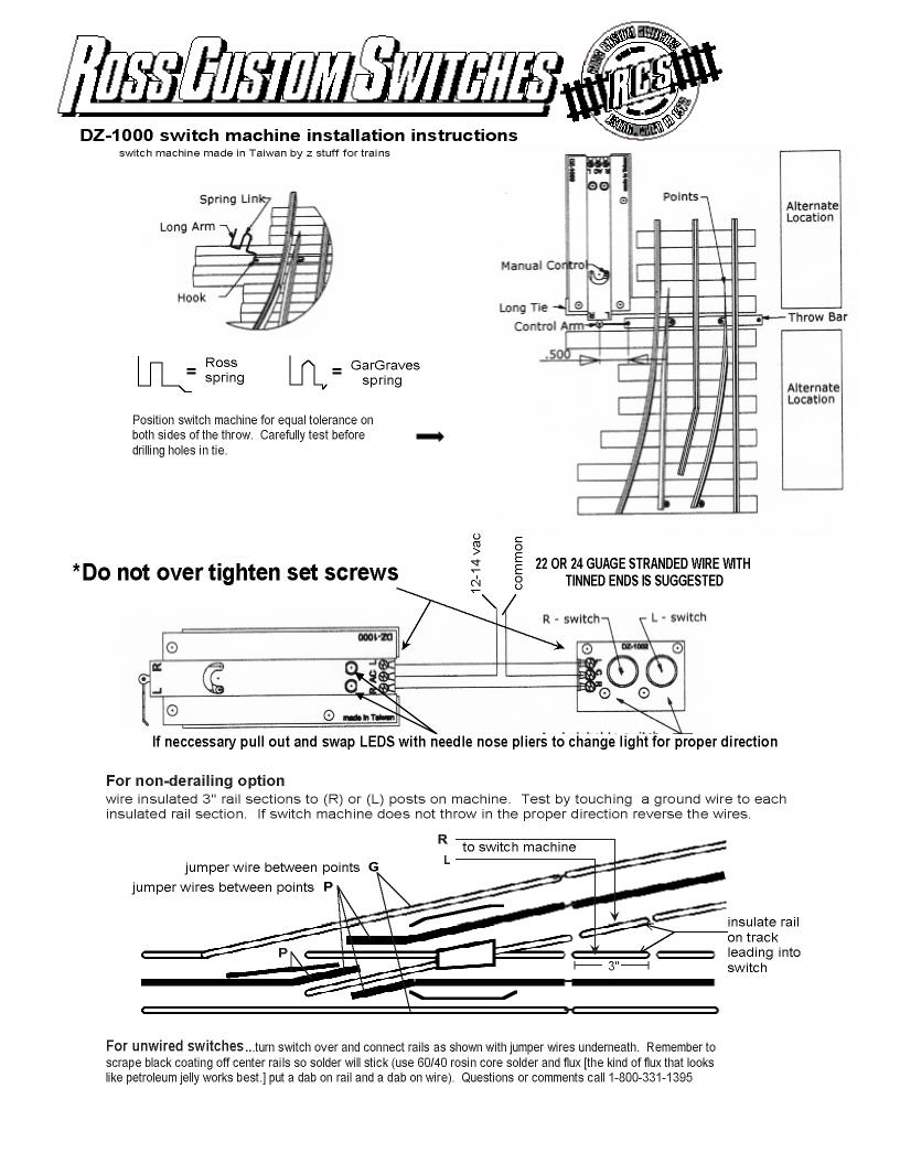
After looking at the instructions for wiring the DZ-1000 for non-derail, it would seem to me that that wires in the diagram are not connected to the isolated trigger rails, which are from the gap to the plastic V.

DZ-1000_Non_Derail

Where have you connected trigger wires?

if those are to be the isolated rails, there needs to be an insulator or gap to the adjoining the track to prevent the common from connecting to track power.

Attachments

Images (1)
  • DZ-1000_Non_Derail
Last edited by Moonman

It is wired per the diagram to isolated rails.  The switches and non derailing are working fine. 

I am not positive that I am checking voltage correctly.  I checked voltage from the center rail (which is powered from the PH180) to the isolated rails, which is grounded to the MTH 1000 via the dz1000 switch machine.  Is this the correct way to check the voltage when the engine crosses the isolated rails?   I just want to make sure my locos are not getting more than 18 volts.  

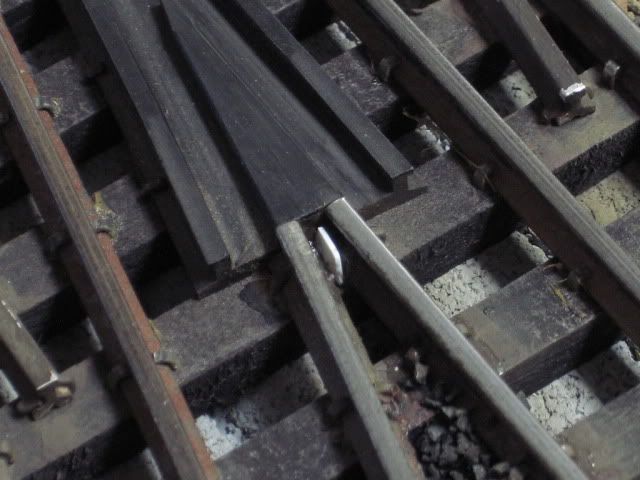
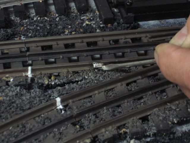
In addition to Carl's note.  On occasion, the two short input rails at the frog can touch.  I pulled some of this Ross switch's track nails, and added a piece of styrene, (white), to correct this problem.

Note the styrene added were the rails would normally join.  Isolation section. Before hooking the two isolation sections to the DZ switch motor.  Check continuity with your meter.  Each isolation section should show (NO) continuity to any other outside rail.  If that is correct, hook to the two DZ switch motor input leads per the diagram.


Last edited by Mike CT
Tanner111 posted:

Joe

You are correct I have two separate circuits with the grounds connected.  At least that's what I'm trying to do.  I looked at the wiring and I don't think I made the mistake you mentioned. I will look at it closer. 

I checked one transformer at a time and only the PH is powering the track. Is that what you mean?  Or do you mean check the voltage on the isolated rails one transformer at a time? Yep - check power to isolated rail one power source at a time. I am getting power somehow from each transformer but just on the isolated rails for that one switch. 

I assume you are isolating one ground rail on each side of the turnout as pictured in the post above and you have the rail isolated on both ends. Please see the attached file. I am asking you to make some voltage measurements under different scenarios.

Joe

Attachments

Files (1)
Model Structures posted:
Tanner111 posted:

Joe

You are correct I have two separate circuits with the grounds connected.  At least that's what I'm trying to do.  I looked at the wiring and I don't think I made the mistake you mentioned. I will look at it closer. 

I checked one transformer at a time and only the PH is powering the track. Is that what you mean?  Or do you mean check the voltage on the isolated rails one transformer at a time? Yep - check power to isolated rail one power source at a time. I am getting power somehow from each transformer but just on the isolated rails for that one switch. 

I assume you are isolating one ground rail on each side of the turnout as pictured in the post above and you have the rail isolated on both ends. Correct.  Please see the attached file. I am asking you to make some voltage measurements under different scenarios.

Joe

Joe,

Since I am using 2 transformers, can you tell me where I should connect the leads on the volt meter to check the voltage?  I am not positive that I am checking voltage correctly.  I checked voltage from the center rail (which is powered from the PH180) to the isolated rails, which is grounded to the MTH 1000 via the dz1000 switch machine.  Is this the correct way to check the voltage when the engine crosses the isolated rails?   I just want to make sure my locos are not getting more than 18 volts. 

Tanner:

You are connecting them correctly. You have a common ground so whether the MTH1000 is on or off won't matter. The voltmeter pos lead always goes to the center rail and the neg lead always goes to one or the other outside rail.

In my presentation when I say connect voltmeter to a point on a rail I mean connect the voltmeter positive lead to the center rail where indicated by the letters and the negative lead to the outside rail where indicated.

Once again all you should ever be seeing is 0 or 18VAC from the PH (off/on). Most of the measurements are with the non-derail ground wire disconnected so the MTH1000 is out of the circuit anyway. Once you connect the ground wire then only the MTH1000 ground should come into play.

Basically with the MTH1000 on and the PH off you should read 0 volts everywhere.
With the MTH1000 off and the PH on you should be reading 18VAC everywhere except the isolated rail.
With the MTH1000 on and the PH on you should be reading 18VAC everywhere except the isolated rail.
Only when the isolated rail is connected to the opposite ground rail through a train truck or a wire splice will you see 18VAC on the isolated rail (pos voltmeter lead on center rail and neg voltmeter lead on isolated rail).

Let know what happens

Joe

Joe

With the MTH1000 off and the PH on you should be reading 18VAC everywhere except the isolated rail.  I have 18 volts on all of my isolated rails including my dz2500's as well  

it sounds like this is my issue but how do I find the cause?  The isolated rails are isolated.  There is no continuity between them and the outside rail.  I also don't see any crossover in the wiring between the 2 circuits.


Tanner and Joe,

I am thinking that the connection shown in the diagram of the Z-1000 common to the outside rail is the problem. See green line and circle. That is the only way the 18v from the PH180 could complete it's circuit is through the switch motor controller. Connect only to the motor controller from the Z-1000.

DZ-1000_Non_Derail


Attachments

Images (1)
  • DZ-1000_Non_Derail

Tanner:

I agree with Carl - If you are seeing 18VAC on all isolated rails with the PH on it is a sure bet somewhere you have crossed wires (connected a ground wire to PH positive). I don't know your wiring scheme so:
1- If you have ground wires from all isolated track going to one terminal then check where the wire from the terminal is going. It may be connected to PH positive.
2 - If you have ground wires from the isolated rails going to various ground terminals then the job is much more difficult because somewhere one or more ground wires are connected to the PH positive.

Worst case you may have to disconnect ALL ground wires, make sure voltage on all track is indeed zero with both the PH and MTH1000 on, then reconnect common ground wires (not the isolated rail grounds) one at a time while measuring voltage on a track rail (middle to inside or outside rail) as you reconnect wire. With both the MTH and PH on you should see 18VAC on all track except the isolated rails which should be zero. Even though the MTH should have nothing to do with the track power circuit leaving it on makes sure both power supplies are truly independent of each other.

Joe

I have a four 14 gauge wires, a hot and a ground for each transformer, going around below the layout.  I have power drops for the track that tie into the PH, and the switches to the MTH 1000.  The switch controllers are together in one corner and tie into the MTH hot in one place.  The switch motors tie into the MTH ground at various locations.  The grounds for the isolated rails connect to that switch's wiring, not directly to the ground from the MTH transformer.  I am missing something.  I'll check it again, and do the worst case if I can't find it.  I appreciate all the help.

I disconnected the hot from the MTH transformer and all the switch grounds that are connected to the MTH ground. I had 0 to .5 volts on my isolated rails. As soon as I connect one ground from one switch controller to the MTH ground I have 13-18 volts on the isolated rails for that switch when I measure voltage from center rail to isolated rail. Does that mean my transformers are out of phase?  When I connect the hot the voltage on the same rails jumps to 37.

Leo my 11 degree switches have isolated leads going into the switch. I'm not isolating the rails on the switch itself. I had the problem of the spikes touching so I had to isolate the track before the switch. 

IMG_0199

Attachments

Images (1)
  • IMG_0199

Tanner,

Extending the trigger rails is ok because it helps with the slow movement of the switch throw.

It appears that you have isolated track power rails. The inner rails are the trigger rails. Are the two trigger rails on the switch touching the frog? Touching one another? Those rails should be isolated from the track power and then extended.

I see the gap on the thru , but the out trigger rail appears to be connected to the extension rail. They should both be connected and isolated at the end of the extension track. (White line) They should not be touching at the frog. That's where the L and R wires attach

Ross_DZ1000_Non_Derail-w_Extension_Zoom

Attachments

Images (1)
  • Ross_DZ1000_Non_Derail-w_Extension_Zoom

The isolated rails are in the track before the switch.  The inside rails on the switch are dead and are not isolated.  They're not even grounded.

I checked the isolated rails and they are isolated.  No continuity to ground rails.

The switch controller is still wired to the switch motor.  The dz1000 controller has a ground wire and the motor has a hot.  I have the ground connected to the MTH 1000 but the hot is not.  As you can see in the picture I am getting voltage to the isolated rail.  I do not know where the voltage is coming from.

Tanner111 posted:

The isolated rails are in the track before the switch.  The inside rails on the switch are dead and are not isolated.  They're not even grounded.

That is how they should be. Those are the trigger rails. They should also not be connected to one another. The track extension piece should be a  continuation of those two rails. The r & L wires attach to those or the extended section. The isolation joint should be where I placed the white lines on the photo.

I checked the isolated rails and they are isolated.  No continuity to ground rails.

The isolated rails must be the inside rails. I see white on the outside rail joint. What is that?

The switch controller is still wired to the switch motor.  The dz1000 controller has a ground wire and the motor has a hot.  I have the ground connected to the MTH 1000 but the hot is not.  As you can see in the picture I am getting voltage to the isolated rail.  I do not know where the voltage is coming from.

This is why I suggested early on to use the 14v fixed terminals on the Z -1000 brick. There could be a Z - 1000 controller issue. 14v won't harm the switch motor or switch controller


Moonman posted:
Tanner111 posted:

The isolated rails are in the track before the switch.  The inside rails on the switch are dead and are not isolated.  They're not even grounded.

That is how they should be. Those are the trigger rails. They should also not be connected to one another. The track extension piece should be a  continuation of those two rails. The r & L wires attach to those or the extended section. The isolation joint should be where I placed the white lines on the photo.  This is good.

I checked the isolated rails and they are isolated.  No continuity to ground rails.

The isolated rails must be the inside rails. I see white on the outside rail joint. What is that?  I dremeled the joint to smooth the connection.  It has a metal rail joiner.

The switch controller is still wired to the switch motor.  The dz1000 controller has a ground wire and the motor has a hot.  I have the ground connected to the MTH 1000 but the hot is not.  As you can see in the picture I am getting voltage to the isolated rail.  I do not know where the voltage is coming from.

This is why I suggested early on to use the 14v fixed terminals on the Z -1000 brick. There could be a Z - 1000 controller issue. 14v won't harm the switch motor or switch controller  I tried this as a test in case the Z1000 was the issue.  It did not change anything.  I may change it but it didn't fix the issue.


What I do at this point is rethink all of my wiring. I disconnect the transformers and perform continuity testing to confirm everything is wired properly.

I have thought that I had things correct and found a wiring mistake before.

It really sounds like something away from this switch is crossed.

Are you really having fun playing with trains now? We say that to one another when trying to resolve these anomalies.


A couple of things this picture would indicate.

The trigger rails should be isolated/insulated from the outside rails.   Red probe, center rail to the isolated section should not be reading 15 volts if that is your track operating voltage.  I prefer to check, all wires disconnected, using the ohm meter function.  The (TWO) isolated rail (Trigger) section with the Ohm meter should show no continuity to any outside rail or for that matter the center power rail.  One lead on a trigger section to an outside rail or a center rail should show infinity or a very large ohm reading.  Also check that the (TWO trigger rails) are not touching each other.

Theory: As a wheel set completes a common outside rail circuit to the trigger section it will automatically switch the switch motor.  Accessory common and Track common being one and the same. Accessory transformer common should be connected to Track power transformer common to assure this.

Tanner111 posted:

I have a four 14 gauge wires, a hot and a ground for each transformer, going around below the layout.  I have power drops for the track that tie into the PH, and the switches to the MTH 1000.  The switch controllers are together in one corner and tie into the MTH hot in one place.  The switch motors tie into the MTH ground at various locations.  The grounds for the isolated rails connect to that switch's wiring, not directly to the ground from the MTH transformer.  I am missing something.  I'll check it again, and do the worst case if I can't find it.  I appreciate all the help.

Tanner:

I misread your post so edited below:

As trainman said - the center post on the DZ1000 'AC' goes to MTH power and the center post on the controller (your toggle switch) goes to common ground. It sounds like you have the DZ1000 center post connected to common ground. From what you said you have the wires from the isolated rails correctly connected to the L and R of the DZ1000 motors. However if it is correct that you have the DZ1000 center post connected to ground then you essentially have the isolated rails connected to ground which renders the 'isolation' null and void. They are now connected to continuous power through either the MTH and/or the PH.
So, if the DZ1000 center post is connected to common ground then you are sending both PH and MTH power through the DZ1000 to the isolated rail. The only catch in this is as what was stated above by Leo. The controller is (as you stated) is connected to MTH power but yet you are still getting MTH voltage on the isolated track. There may be two issues at play here.
1. The DZ1000 is connected to ground not MTH power and the controller is connected to MTH power not ground plus
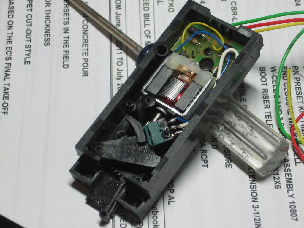
2. voltage is leaking through the LED on the controller. D. Zander has had issues with some red LEDS being 'leaky'. The sure way to stop this is to pull the LED out and see what happens.

In general terms (hopefully I have this straight) the MTH has noting to do with powering any track rail including the isolated rails. It only powers the DZ1000 switch motors. The PH powers all track rail. They may share a common ground but their power lines go to different 'circuits'. It is like your TV and your microwave. They share the same ground but turning on your TV (track power) does not turn on the microwave (DZ1000 motors).

One last item - I could not see from your photos. Please make sure you have plastic joiners on both ends of your isolated rail. If you have one end connected to the next track with metal and the isolated wire mistakenly going to ground than you are adding track power (PH) to MTH power when you turn on both power supplies.

Keep us posted

Joe

Last edited by Joe Fauty
 

As trainman said - the center post on the DZ1000 'AC' goes to MTH power and the center post on the controller (your toggle switch) goes to common ground. It sounds like you have the DZ1000 center post connected to common ground. From what you said you have the wires from the isolated rails correctly connected to the L and R of the DZ1000 motors. However if it is correct that you have the DZ1000 center post connected to ground then you essentially have the isolated rails connected to ground which renders the 'isolation' null and void. They are now connected to continuous power through either the MTH and/or the PH.

I did this from memory and noticed what I said was wrong when I looked at it last night.  The center post on the switch controller goes to MTH ground (which is also connected to PH ground).  The red wire on the DZ1000 switch motor goes to hot on the MTH transformer.   The non derail feature works.  I am just getting high voltage on the isolated rails.  The green lines show what I have isolated for this switch.  There is no continuity from these to any outer rails or the center rail.

Attachments

Images (1)
  • mceclip0

Tanner:

Try setting a car wheel set across the isolated rail (or a wire) so that the outside rail (the common AC ground) completes the circuit to the switch machine. The circuit is MTH AC HOT to the center terminal of the switch machine, through the coil inside the switch machine, thru the wire to the isolated rail, thru the wheel set to common AC ground.

With the wheel set completing the circuit, measure the AC voltage across the center rail to the isolated rail. You should get track voltage.

Apparently what is happening is that some of the MTH hot is leaking thru the coils to the isolated rails which are floating. The voltage you see with nothing to anchor the isolated section down is track voltage plus some from the leaking coils. This is most likely low current; not enough thru the coils to throw the switch.

If that's true, you have it right and should be able to run engines through without a problem.

Consolidated Leo posted:

Tanner:

Try setting a car wheel set across the isolated rail (or a wire) so that the outside rail (the common AC ground) completes the circuit to the switch machine. The circuit is MTH AC HOT to the center terminal of the switch machine, through the coil inside the switch machine, thru the wire to the isolated rail, thru the wheel set to common AC ground.

With the wheel set completing the circuit, measure the AC voltage across the center rail to the isolated rail. You should get track voltage.

Apparently what is happening is that some of the MTH hot is leaking thru the coils to the isolated rails which are floating. The voltage you see with nothing to anchor the isolated section down is track voltage plus some from the leaking coils. This is most likely low current; not enough thru the coils to throw the switch.

If that's true, you have it right and should be able to run engines through without a problem.

Leo

this appears to be what is happening.  With a truck on that section of track, I get track voltage. I don't know how you knew that but that info gives me some comfort that I don't have an issue. Thank you and thanks to everyone that read my post and offered their expertise!

Add Reply

Post

OGR Publishing, Inc., 1310 Eastside Centre Ct, Ste 6, Mountain Home, AR 72653
800-980-OGRR (6477)
www.ogaugerr.com

×
×
×
×
Link copied to your clipboard.
×
×