OK, I apologize for the slow uptake on what you're trying to do. Some comments then.
1) I don't know if there's an official definition, but the 751D circuit in the link is not really a Capacitive Discharge circuit as the term is used for O-gauge switches. That is, the energy to throw the switch is not being stored in a capacitor. Instead the circuit uses a capacitor (and resistor) to turn on a transistor for a brief amount of time. The energy to throw the switch is coming from a "beefy" 12VDC power source. The circuit is such that the momentary switch to pulse the switch coils can be held down and you only get one pulse per button press.
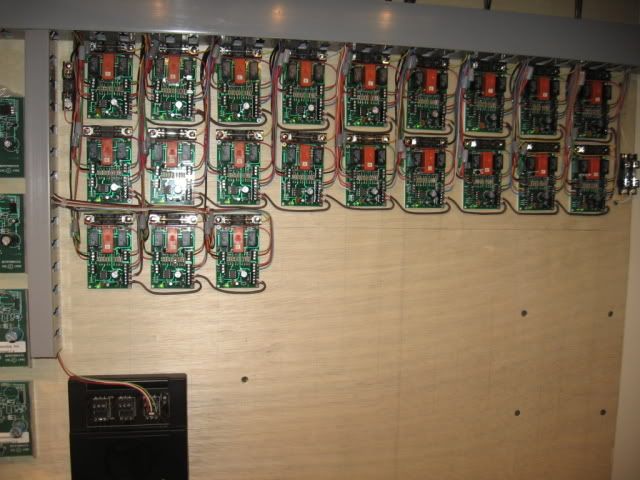
2) The AIU, when configured in the two output switch configuration, is performing the same function as the 751D circuit. That is, the energy is not being stored in a capacitor. Instead the AIU has internal timing circuit to briefly pulse the switch coils.
3) So one approach is to have the AIU relays momentarily pulse DC voltage of sufficient magnitude to drive your Atlas coils. Presumably this would be something more than 12V - maybe 16V DC or more based on your comments. This same 16V DC supply would power the 751D circuit modified to handle more than 12V DC. This is a simple modification choosing capacitors with slightly higher operating voltage (e.g., 25V type instead of 16V type). The transistors would also be selected to operate at more than 12V. These are trivial changes which probably won't even add to the cost.
4) By using a common supply for the AIU and the 751D circuit, they can operate in parallel so you can have DCS-AIU control at the same time as the momentary manual pushbutton switches for the kids. Again, the AIU provides only a momentary pulse to fire the coils for command operation, and the 751D circuit provides only a momentary pulse to fire the coils for manual operation.
5) To handle the LED feedback/memory problem, simply use a latching relay. The latching relay has a "set" coil and a "reset" coil. Parallel the latching relay coils with the two Atlas switch coils. So whenever one Atlas coil is driven, the mating latching relay coil is driven too. Simply attach the desired red or green LED to the output of the corresponding contacts of the latching relay to indicate position.
6) You could even use the 751D circuit board if hand-wiring the circuit is inconvenient. That is you wouldn't install the components associated with the LEDs since the LEDs would be driven by the latching relay outputs and it appears you want the single-package 3-pin bi-color LEDs anyway.
7) I really think it would be cool if you could figure out how to modify the Atlas switch with some kind of cheap sensor to indicate the actual mechanical position (like the Realtrax switches). But if that's not in the cards, then so be it. Presumably Atlas has been bombarded with this request so if they haven't done it perhaps there's good reason.


