On the Super Duper Chief thread I discussed running into the 10 amp limit on a single output and the problems it caused.  someone suggested paralleling to outputs - keeping the output about the same on each and it might work to give me 20 amps instead of just 10. 


Anyone done this?  Anyone have any opinions or know why it would not work/would lead to disaster.   I'm an electrical engineer and I've paralleled a lot of power sources (impedance matched power transformers into a single bus,  micro-turbine generators at the same site, etc) in my time, so even though it probably would work, maybe I worry to much about all the little things that can go wrong.  Thought I'd ask before perhaps hazarding my ZW-L.  

Original Post

Replies sorted oldest to newest

What is the internal wiring of the unit?  Is the 10 amp limit per channel an artificial barrier to meet UL/CPSC restrictions?  The unit is supposed to be able to share 620 watts across all four channels "dynamically".  If you "parallel" two channels will that confuse the dynamic power limiting capability build into the unit.  


Given the cost of the unit a pair of 180 watt bricks and a TPC-400 may make more sense.

Lee

In the distant past I have successfully paralleled two 180 watt PoHos linked to a TPC 400 to achieve the so-called "super power" as well as a pair of 135 watt units linked to a TPC 300 [originally shown in a IC Controls video demonstrated by Lou Kovach and produced by the OGR Webmaster].


Although my 180 watt units, equipped with TVS, had a very quick acting breaker, at the higher amperage loads I still got  a very significant arcing upon a derailment pre-trip. It did leave marks on the rails. [O-gauge welding].


As Chuck notes control of the your 180 linkage depends on the circuitry of the ZW L?


The paralleled 135 watt units linked to a TPC 300 producing 15 amps were far more practical for my use. However, the 135s do not trip nearly as fast as the 180 units.


In any event only fixed voltage transformers should be paralleled. According to Davis Electronics, Jim Barrett''s employer way back in the early days of paralleling PoHos, circulating currents can develop in pairing variable voltage transformers.


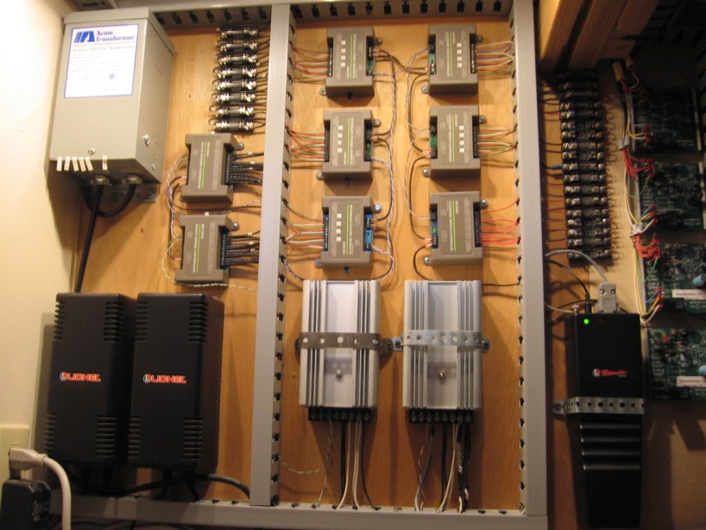
Photo below of my 1997-built layout's control "panel"  shows the array of Powerhouses and Track power Controllers that I experimented with. In the end, for my layouts, I settled on 10 amps per power district, each supplied by a single 180 watt PoHo.

[the two 180 watt units on the lower shelf with the red and white labels on the end, were the early issue "out of phase" PoHos that I opened and rephased--as so marked]..


100_1090-002


Attachments

Images (1)
  • 100_1090-002
Last edited by Dewey Trogdon
Originally Posted by N.Q.D.Y.:

Isn't that a bit like 'crossing the streams' in Ghostbusters? 


Dr. Egon Spengler: There’s something very important I forgot to tell you.
Dr. Peter Venkman: What?
Dr. Egon Spengler: Don’t cross the streams.
Dr. Peter Venkman: Why?
Dr. Egon Spengler: It would be bad.
Dr. Peter Venkman: I’m fuzzy on the whole good/bad thing. What do you mean, “bad”?
Dr. Egon Spengler: Try to imagine all life as you know it stopping instantaneously and every molecule in your body exploding at the speed of light.
Dr. Ray Stantz: Total protonic reversal.
Dr. Peter Venkman: Right. That’s bad. Okay. All right. Important safety tip. Thanks, Egon.

My Grandsons and I love that movie, all of the Ghost Busters movies!

I like to think of it as welding 101.  I have a relatively small Parallel track power system supply using PH135's, each with a reset of 7.5 amps, (so parallel, I assume that to be 15 amps), I have tripped both these resets simultaneously.  Usually on a de-rail there is enough time delay that there is significant arc and spark, chewing-up wheels and track before power is gone. I installed 7.5 amp fuses in every track block and left the welding to others.

I have a 12V transformer that has two 120V primaries and two 12V secondaries in one transformer.  They are designed to be paralleled and work great, providing 20 amps that I use for all accessories on the layout.


My only concern would be if the transformers have separate AC plugs and outputs.  If the secondaries are tied together and one transformer is unplugged, the male AC plug would have 120V on the exposed prongs.


The first transformer would drop 120V to 18V, and the second would take the 18V and step it back up to 120V because the secondaries are tied together.


Ed


Ed

Originally Posted by N.Q.D.Y.:

Isn't that a bit like 'crossing the streams' in Ghostbusters? 

Yes, just a bit like crossing the streams. On reflection, getting my Super Duper Chief going is not so important to me that I will take any chance on ruining my ZW-L, so I'll be putting it back up on for now.


RickO - absolutely right about the Pullmor motors, except, well, I have an ATSF Anniversary set with four of them that I treasure, and a postwar A-B set that has another.  It's sort of like owning a car with a carburetor (I imagine half of the folks on this forum own one, as I do): it's a problematic, fussy device that at best does a poorer job than modern fuel injection, but when it's in a car you dearly love . . . 

Your Pullmore's aren't helping but the real hogs are the incandescents in the 14 trailing passenger cars.  I'd focus on "fixing" that before messing with the motors.


BTW, I've looked at some photo's of the Supper Chief with extra head end power.  I've seen photo's of ABBBA and ABABB.  There was even one of AAABBB.


Originally Posted by wb47:
Does not the tpc 400 allow for two 180 inputs? Yes Lionel part 6-14194 (Cable set) has a connection part that plugs in (2) PH180's or PH135's to a (2 terminal forked spade) end designed to hook to the Input terminals of a TPC 400.   Would this be paralleling and doubling the amps? Yes.  Limit is the 20 amp reset on the TPC. I believe each PH180 has a 10 amp reset.   Thanks

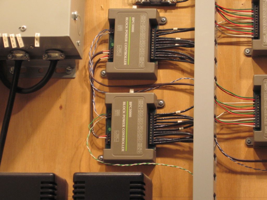
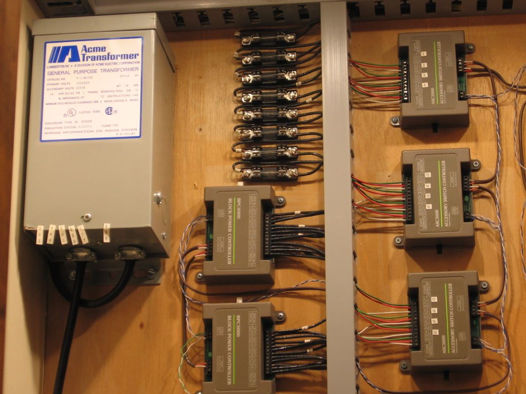
Output of the TPC is then the input to BPC's (Block Power Controller).  Each BPC has (4) track outputs.  Note the (8) fuses (7.5 amps) one for each of the (8) track circuits from one TPC.
 
TPC's lower right, note the black/white twisted pair Cable set on the right TPC that parallels the input of the PH135's lower Right.


Output of the (2) TPC's pictured is the Input to the (2) BPC's pictured near the large accessory transformer upper left.   


Output ((8) Track circuits) are fused via the (8) 7.5 amp fuses pictured.

Fuse blocks are from Grainger supply.  7.5 amp fuses are available at local auto parts stores.
Last edited by Mike CT

If you power blocks from separate outputs and then you pass from one block to another, the two outputs are tied together while the locomotive is bridging the two blocks. I have not heard of this causing any problems even if the two outputs are not adjusted to the same settings. I have seven blocks on one loop each powered from a separate new ZW output. I have never had any problems caused by crossing blocks.

Originally Posted by RickO:
Originally Posted by Erie_Lackawanna:

<<<<<<  Loves those "Crummy Prehistoric Pullmor's"  I wonder if in 60 years there will be more of those 120 year old pullmor's or those 60 year old can motors?? ROFL!!  

When your  long dead, what does it matter if your trains are still running??....ROTFL 


I'm taking mine with me...you never know!..........

I have the Santa Fe Anniversary Set as well. My powered units run hot. Soften the paint on the trucks hot. There is something wrong with the TMCC boards in my set. I disconnected the TMCC unit and wired the motors directly off the track. The motors ran quite cool when running directly off the track. However, when I reconnected the TMCC boards, the units ran hot once again. Thus, there is something wrong with the TMCC boards in my units. I am not quite sure what; either the boards starve the motors for current or there is high internal resistance in the boards for some reason.  Regardless, I will fix sometime in the future. 


In the literature supplied with the set it says that the entire set, ABBA + 7 cars (2 powered units, one railsounds unit, 2 dummy units) draws 7 and a half amps.  


My 2343 usually gets the duty to pull the 7 aluminum cars plus the railsounds B unit. 2343 pulls the seven cars plus two reefers, the railsounds B unit and dummy A with ease. 

Last edited by WBC

I have had no heat or other runnning problems with my ATSF anniversay set as you have WBC, but mine set, run as the set with no additional cars, etc, demands closer to 9 amps than 7 when running at speed.  It alone (no other locos or cars) blinks the red light for about three seconds when starting out, then stays above eight amps as I slowly accelerate it with more throttle.  At speed - a scale 85 or so, it wants about 8.5 - 9 amps for around 140 watts total,  I have a ZW-L which is a challenge to read to within more than half an amp, so I can't determine itany finer than that.

Lee, as an electrical engineer wouldn't you feel better paralleling transformers, then running them through a single thyristor control much like the dual 180s through a TPC400? I can't imagine that there's any way to synch the outputs of two modern ZWs. I would think you could develop some high transients due to the timing of the waveform, right? Might want to ask Jon Z!


I tend to think 20amps to the track is a bit nutty, any more current is pure doom.


"Super power", as we called it [20-22-amps capacity when paralleled], can definitely put a hurting on ones rails and wheel sets. I experimented on a 16' test track by intentionally derailing and dragging cars for only a few couple of seconds at 15 amps and then at 20. Lot of flash and burn at both levels.


It does risk damage but I can understand why one might do it when running on a unusually large layout with multiple long lighted passenger consists in the same power district. As suggested earlier, if one can afford the expense and sometimes troublesome removal of passenger car bodies, converting to LEDs is the best answer to reducing consumption.


Last edited by Dewey Trogdon

Lee,


Similar to Dewey's set up, before the current configuration, we used pairs of 180W and 135W PH 'bricks' connected through TPC400 and TPC300 controllers on the South Hills display layout. We ran powered PW 2333 A-A-A-A lash-ups with 12-15 lighted cars on the outter loops (2% grade between front and back of layout) using the TPC400 with no problems at all.


Originally Posted by Lee Willis:

 I'm an electrical engineer and I've paralleled a lot of power sources (impedance matched power transformers into a single bus,  micro-turbine generators at the same site, etc) in my time, so even though it probably would work, maybe I worry to much about all the little things that can go wrong..  

There is a world of difference between industrial power distribution and model trains. As a fellow Electrical Engineer, I would advise that you go with your first instinct. If it doesn't sound like a good idea, it probably isn't.


Does Lionel provide documentation showing parallel output configuration? The ZW-L is an expensive transformer and as such would be a poor candidate for any experimentation. Mike Reagan has a reputation of being a really good guy, but I wouldn't want to approach him with repair of a smoked ZW-L (especially after this discussion).


When the load exceeds capacity, reducing load is the best place to start. Just my $0.02.


Gilly

Originally Posted by Norm Charbonneau:

Lee, as an electrical engineer wouldn't you feel better paralleling transformers, then running them through a single thyristor control much like the dual 180s through a TPC400? I can't imagine that there's any way to synch the outputs of two modern ZWs. I would think you could develop some high transients due to the timing of the waveform, right? Might want to ask Jon Z!


I tend to think 20amps to the track is a bit nutty, any more current is pure doom.


Norm is correct, paralleling transformers cores and running them through a single output controller is the only way to go.  Connecting 2 outputs on the ZWL is potentially going to do damage, as this is *after* the output controller.  Any variation in the two channels will stress the outputs.

From a previous post two bricks ( fixed voltage Transformers) hooked to a TPC (Track Power Controller)

Lionel part 6-14194 (Cable set) has a connection part that plugs in (2) PH180's or PH135's to a (2 terminal forked spade) end designed to hook to the Input terminals of a TPC 400.  

You still have to deal with the high amperage output.  IMO, fuse track feeds down to no more than 7.5 amps.  

Last edited by Mike CT
Originally Posted by Gilly@N&W:
Originally Posted by Lee Willis:

 I'm an electrical engineer and I've paralleled a lot of power sources (impedance matched power transformers into a single bus,  micro-turbine generators at the same site, etc) in my time, so even though it probably would work, maybe I worry to much about all the little things that can go wrong..  

There is a world of difference between industrial power distribution and model trains. As a fellow Electrical Engineer, I would advise that you go with your first instinct. If it doesn't sound like a good idea, it probably isn't.


Does Lionel provide documentation showing parallel output configuration? The ZW-L is an expensive transformer and as such would be a poor candidate for any experimentation. Mike Reagan has a reputation of being a really good guy, but I wouldn't want to approach him with repair of a smoked ZW-L (especially after this discussion).


When the load exceeds capacity, reducing load is the best place to start. Just my $0.02.


Gilly

That was basically what I was trying to say.  As an EE, while I paralleled many power sources, they were always engineered beforehand with an awareness of all the factors and equipment characteristics.   There are so many things that might go wrong when you don't go through all that I can think of: probably would not happen, but . . . .  IF if were important to do this, then I'd take the chance, but merely to get a fun, if silly train started, a train I won't normally be running?  No, its not worth it.  


Last edited by Lee Willis

Lee 

Generators do tend to " boogie" when paralleled out of sych. My experience was with bringing generators up to take the load, parallel, etc, including with shore power prior to going "cold iron" shipboard for maintenance.


My predecessor as Duty Sparktrician on on the electric drive DE, USS George was going to show a newbie just out of Navy EM School how to parallel with Yard shore power at the Destroyer Yard in San Diego prior to taking ship service generators off line. Problem was he failed to strip an agreed upon portion of the ship's load to comply with available yard capacity and knocked the Yard powerhouse off line. Turns out he had never performed the task before. He never got another chance---was being transferred to White Sands,N.M. out in the desert.

I still remember the Engineering Officer stomping his hat.

Last edited by Dewey Trogdon

I'm not sure you can hijack a dead thread, but here goes.  Earlier in this thread there was a discussion on having two 180 PoHos linked to a TPC400.  I plan to do this, but will have a 15 amp fuse between the TPC and the track.


My operational plan is to have only one PoHo on unless I need the extra power, then I will turn both on.  I need the extra power for the same reason Lee does (someday I will replace all the K-line Streamlighting but not now).


My concern is the issue Ed discussed; “If the secondaries are tied together and one transformer is unplugged, the male AC plug would have 120V on the exposed prongs.  The first transformer would drop 120V to 18V, and the second would take the 18V and step it back up to 120V because the secondaries are tied together.”  According to Dewey, the “…TPC board could be energized at horsepower under the described feedback condition.”  Could or would?


If possible, I’d like to get a definitive answer to this.  Can I safely turn off one PoHo and leave it connected to the TPC, while the other provides power to the TPC?  Or do I need to unplug the unused PoHo if not using it?


Thanks.


Ron

Post
×
×
×
×
Link copied to your clipboard.
×
×