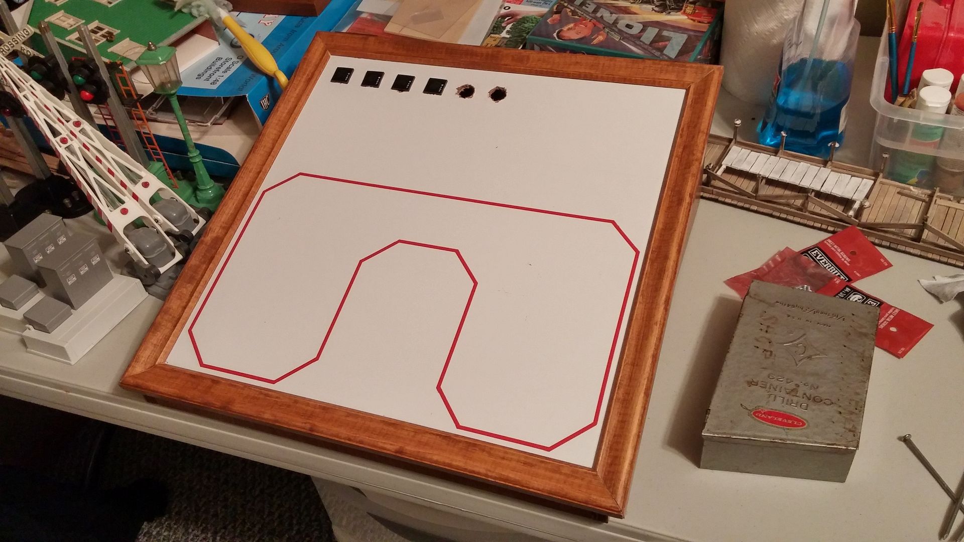
At some point soon, I hope to build another layout. If you have a layout with a track diagram what did you use to make it? I'd rather not need to buy software. For my last layout I spray painted a piece of metal, used yellow first then taped it and used black to respray. I've seen others just use what looks like pinstriping without any painting with good results...any tips?


Tom


tom_panettiere_05

Attachments

Images (1)
  • tom_panettiere_05
Last edited by PRR8976
Original Post

Replies sorted oldest to newest

My current one is made with RR-Track software and enlarged at a vendor, but my original one some years ago was done in several steps.


I covered a board with clear contact paper, then drew the layout on it using straight edges and a drafting tool called a French curve, enlarged the lines with yellow paint.  Then after it was dry, I cut out around the track diagram with an Xacto knife.  Then I spray painted the whole board black.  When dry, I peeled off the remaining contact paper that covered the track diagram.  This left the track outline yellow on black.


Whew.  A lot of work.

.....

Dennis

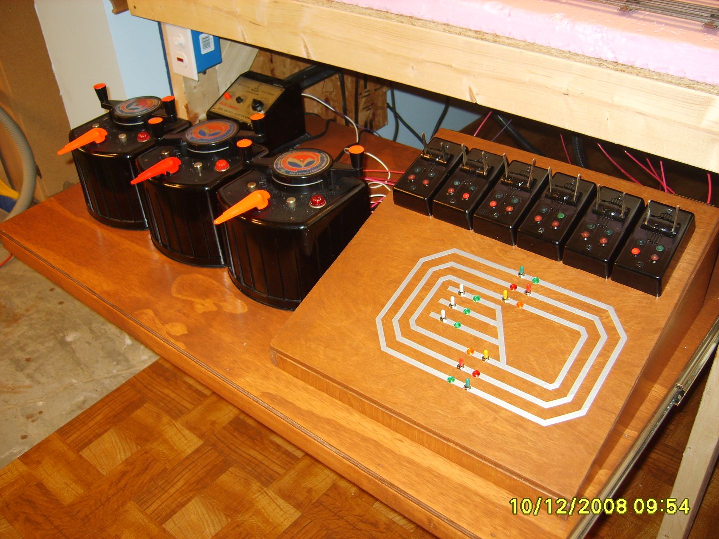
Masonite 1/8 inch and 1/8 inch auto pin striping, still going strong after 40 years.


The green push button switches are main line and red alternate routes to throw the Marx switch.  The blue button switches are uncoupling magnets.  Some throw Marx switches in pairs. 

The slide switches shown are for block control and show white when on and black when off. 


These are the dreaded Radio Shack switches and several of the push buttons have had to be changed over the years as the current draw of the Marx switch magnets is over their rating. 

 No big deal as two small screws at the base hold the panel down and it fits in a groove at the top and just swings out with a foot or so of slack in the wires.  The wires are pigtailed with 18 inch of light gauge, more flexible wire.


I like a hard wired control panel as it is easy to use, easy to trouble shoot, easy to build and fits into my 1950 era layout. 

It is what most boys that just had a transformer and 5 or 6 Lionel turnout switches just screwed or nailed down to a board as a 50s kid dreamed about.


Charlie


Train Complete 1-17-2015 152

Attachments

Images (1)
  • Train Complete  1-17-2015 152
Last edited by Choo Choo Charlie

I made my track diagram on PowerPoint using different colors for each mainline and sidings. Printed it on card stock.  Purchased a clear plastic "lean to" photo frame. Cut off one pane and sandwiched the diagram between it and a sheet of .025 aluminum sheet (two layers of plastic would be too thick for micro switches).

I used automotive pin stripping  on my old control panel and now on my new one.  I had real trouble with the curves though, I could make the tape bend but the curves were all whopper jawed.   So, I opted for this, plus I think it looks a little neater.


Old control panel....


New still under construction control panel....


Paul

I agree. Youtube has some really good tutorials. In fact, I recommend the tutorial by Mike Fifer. Rather than using pinstripes, he uses thin styrene stock on an acrylic sheet to make a 3 dimensional panel and then highlights the different routes with paint pens. I tried a simpler version of it (no switch controllers) and his technique works very well. Like you, I just couldn't get the pin striping to come out right.

I'm in the process of building my first permanent layout and I am wanting to plan for a "track diagram".  Is there a tutorial anywhere that would explain all the options for what you are doing with the panel such as light indicators, switches, etc.?  What do the lights and the colors signify.  I assume that they indicate switch position, but what is the standard as far as layout and color.  Does one place a toggle (or pushbutton) by the switch on the diagram to control the switch?  What about the lights on the track where there is no switch... Does this indicate power?  If so, is there a standard for color?  I guess I am looking for a set of standards for laying out the panel.  I would assume that you would want anyone to walk up to your panel and be able to control the layout.  I hope I didn't ramble too much, but I'd like to do this right.  Thanks!

TM Video just did a shoot and will be out shortly.  Many of the control panels are over 30 years old.  The key to making them user friendly is to hinge them on the bottom and tilt them out from the top.  One last thing, Formica gives a real finished look.  If people want, I will try to get some recent pictures that have not been seen before.

Last edited by Marty Fitzhenry
Originally Posted by PaulG:

I'm in the process of building my first permanent layout and I am wanting to plan for a "track diagram".  Is there a tutorial anywhere that would explain all the options for what you are doing with the panel such as light indicators, switches, etc.?  What do the lights and the colors signify.  I assume that they indicate switch position, but what is the standard as far as layout and color.  Does one place a toggle (or pushbutton) by the switch on the diagram to control the switch?  What about the lights on the track where there is no switch... Does this indicate power?  If so, is there a standard for color?  I guess I am looking for a set of standards for laying out the panel.  I would assume that you would want anyone to walk up to your panel and be able to control the layout.  I hope I didn't ramble too much, but I'd like to do this right.  Thanks!

Paul


I'm not aware of any "industry standard", its mostly personal preference. In our case, since we were going to have multiple panels around the layout, it was important for us to have a standard so that members could move from panel to panel and understand how things work.


Here is a more close up picture of the panel I showed earlier in the thread. My personal preference is to put the indicator lights and the toggle switches along the path of the track as shown by the pinstripe tape. This makes it easier to operate especially with a complex panel like this one. You just run your finger along the route you want to take and make sure the power and switch direction lights are light. If you come to a detection light that is light, it means the path  is blocked.


We use amber lights for detection. We use red and green for switch indication. We use blue and/or white for power on/off


The pinstripe tape is also color coded. White is yard tracks. Black and blue are mainlines. Red shows where control is being passed to a different panel.


Hope this helps


IMG_3284

Attachments

Images (1)
  • IMG_3284
Last edited by tr18

Guys, a panel is a lot of work to do it right.  Use Formica over Masonite as it makes cleaning with Windex very easy.  Do not and I repeat DO NOT use Radio Shack switches.  I know many will attack me on this statement.  The big thing is the tilt out ability from the top.  If you ever need to work on a switch or LED, just tilt the top out and have clear access to them.   Do it one time and do it right.  A big layout demands good products so you can keep moving forward and not going back to repair/replace components.


What John does it a good way to go.  Very user friendly.

Last edited by Marty Fitzhenry

Hello,

I used RailModeller (Macintosh) to design my layout and used its capabilities to do a track plan with the appropriate colors for each direction of the main line and sidings. I used a graphics program to make a pdf file in the dimensions that I desired and saved the file to a CD. I took the CD to Kinkos to have the layout printed on a sheet of self-stick label paper of the applicable size. The label was stuck to a sheet of plastic and the holes were drilled to hold the switch actuators, the LEDs and switches for power to the sidings.

I think that I got this information from a Jim Barrett article.

Originally Posted by MichRR714:

Can someone recommend a good SPST lighted toggle switch (preferably LED) and a source?   I've looked around some sources shown in other threads I searched on and have not found what I am looking for.

Have you tried www.allelectronics.com I get a lot of stuff from them.


 I found this one on their website

http://www.allelectronics.com/...-switch-green/1.html

Last edited by tr18

For gluing pinstripe down I do not trust the stickum on the back and use Glass, Metal & More which is clear or Pliobond which is brown and not as easy to hide.  Try local hardware stores or Hobby Lobby type store, or ebay.


For switches I have had to give up on Radio Shack.  I use lots of different types in trains and setting up and repairing vintage stereos. 

Lately I have found ebay to be a good source, with many choices.  I use the search function and look for By it Now and Free shipping!


Charlie

Last edited by Choo Choo Charlie

First of all with all the handheld and iPad programs a control panel is not needed.

However, I like them.


I did mine with CorelDraw.  I added the track and labels for the switch locations; then made a Reverse mirror image as Corel can do and used it on the reverse side of the panel so that wiring was much easier.

So my panel consists of a sandwich of a 1) plex top drilled for the switches and toggles then 2)the Corel draw layout on a 3) thin metal sheet and 4) the reverse CorelDraw image. Each layer was drilled at the same time as the plex.

I used RailModeller to print off a color diagram which I then took to Kinkos. They were then able to take a photo, re-size to my liking and then laminate it.  It wasn't vey costly, $20 or so as I remember.  I then put this laminate on to masonite and added my switch controllers.  A little crude but it works for me.


IMG_0720 - Version 2

IMG_2640 - Version 2

Attachments

Images (2)
  • Laminated Layout
  • Layout W/Switch Controllers

Small, crude and simple  9x16 around-the-wall layou.....


I used white vinyl shelf liner[initally, paint later] and auto pin striping for the track schematic on my simple, small 9x16 layout. It has two power districts; 1] the black pin striping tape represents the outer mainline w/2 spurs and 2] the red stripe is the inner main and Service Yard trackage.


All told 17 track switches with 12 VDC Tortoise Motors controlled directly by Toggles which are placed on the schematic at the pinstripe intersection of the"out" and "through" legs of the turnout. Therefore the position of the turnout is indicated by orientation of the Toggle handle---whether thrown to out or through. Sitting on my senior citizen's stool I know at a glance the position of remotely located turnouts without use of LEDs.[eliminates all the Cab 1 iterations with 7 ASC Modules for 28 turnouts on dismantled layout down the hall]. 

IMG_1782

Attachments

Images (1)
  • IMG_1782
Last edited by Dewey Trogdon

Add Reply

Post
×
×
×
×
Link copied to your clipboard.
×
×