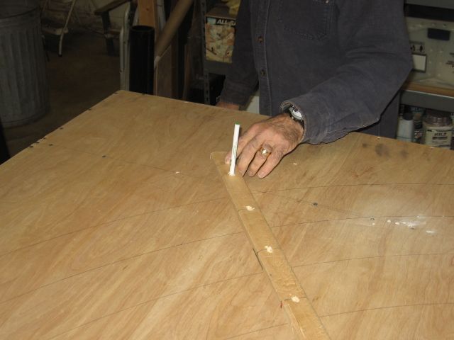
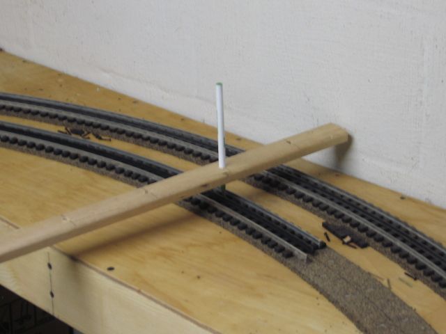
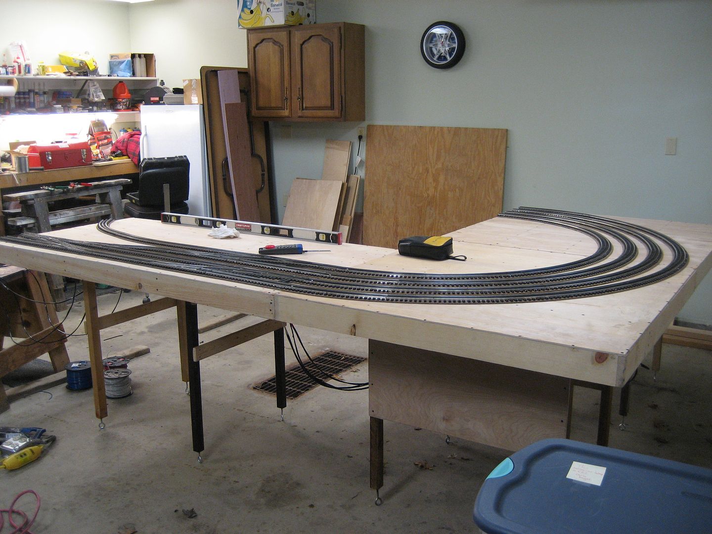
I use two sided jigs that I have made to make my track curves as smooth and consistent as possible.The jigs are made from 1/2" MDF.  Each jig has two radii for each curve radius that I will need. Those radii are 72", 80", 88", 96", 104", 112", 120". AS an Example for O-96" I made the top of the jig radius 46 15/16" and the bottom radius 49 1/16". They are 48" long, and close to 4" wide. The lessor radius is always on the top and the greater on the bottom. This arrangement allows me to bring the ties in contact with the jig from the outside, or the inside of the curve. The track ties can be brought into contact with bar grip clamps and fastened down as you proceed.


Jig Radii     Top (inside)    Bottom (Outside)

72"             34 15/16"       37 1/16"

80"             38 15/16"       41 1/16"

88"             42 15/16"       45 1/16"

96"             46 15/16"       49 1/16"

104"            50 15/16"       53 1/16"

112"            54 15/16"       57 1/16"

120"            58 15/16"       61 1/16"


The radius can be cut by following the circumference tool's drawn line as shown. Or if available use a Festool jig saw with the special curve cutting attachment.


If I am laying parallel tracks. I use an addition jig that will allow the appropriate inter-track clearance. Or, I use multiple, equal sized blocks, (6 to 8) every 3 or 4 ties off the original installed curve. This option allows easy installing of curves that are not the standard size radii. instead of 96" you might need 94 1/2" radius, which would require a set of 2 5/8" blocks between the 104" radius ties and the desired 94 1/2" radius curve vs the 1 7/8" for the 96"radius curve.


 Group of Jigs 

 80" 88" 96" 104" 112" 120" and 72" (Not Shown)


Group of Jigs 80


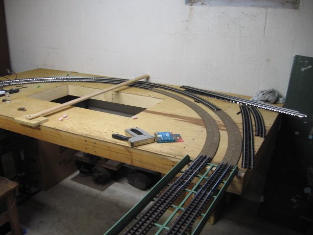
The start of the Double Main Curve


IMG_2540


Base for Double Main Curve


IMG_2541


Final Check of main. 

That it is consistent, straight, and equal distance from edge


IMG_2548


Jig Use

The jig is screwed down on both ends

IMG_2546

IMG_2549


IMG_2550


IMG_2551


IMG_2552


IMG_2553


IMG_2554


IMG_2555


IMG_2557


Clamping 

Clamping makes mating of new section easy and smooth.

IMG_2558


Mated Sections

I usually have to tap the far end on individual rails to get them tight and a smooth curvature.

IMG_2559


Outside Main Completed


IMG_2560


Starting Inside Main

Jig placed and assisted by clamping

IMG_2588


Setting Inside Jig


IMG_2585


Alternative method is to use a multiple blocks against the first set curve.

This works very well if you want a non conventional radius size like 86" or a 74" radius.

IMG_2586


Completed Inside Main Curve


IMG_2589


The Real Test

Do I have enough clearance between the Big Boy and The Allegheny and Lionel Auto Carrier and Atlas 21" CZ. The tightest issue I have is the Big Boy and the Lionel Auto Carrier (on the outside Track)


IMG_2590


Do I have enough clearance between the Big Boy, The Allegheny, Lionel Auto Carrier and Atlas 21" CZ. The closest is the Big Boy and the Lionel Auto Carrier


Thanks for Looking

Buzz

Attachments

Images (21)
  • Group of Jigs: 80" 88" 96" 104" 112" 120" and 72" (Not Shown)
  • The start of the Double Main Curve
  • Base for Double Main Curve
  • Setting Jig For Curve
  • Final Check of main.: That it is consistent, straight, and equal distance from edge
  • Jig Use: The jig is screwed down on both ends
  • Jig Use: The jig is screwed down on both ends
  • Curving Track: The track is adapted to jig by gradually pressing the tie ends to the jig.
  • Tightening adaptation: Tightening adaptation before track is screwed down. The use of clamps makes it easy and smooth.
  • Using Clamp To Assist
  • Track End Fastening: Track fastening the end of the 3 ft section
  • Squaring End of Section: I use a Dremel with a metal diamond embedded wheel.
  • Starting Next Section
  • Clamping: Clamping making mating of new section easy and smooth.
  • Mated Sections: I usually have to tap the far end on individual rails to get them tight and with a smooth curvature.
  • Outside Main Completed
  • Starting Inside Main: Jig placed and assisted by clamping
  • Setting Inside Jig
  • Alternative method is to use a multiple blocks against the first set curve.: This works very well if you want a non conventional curve size like 86" or a 74".
  • Complete Inside Main Curve
  • The Real Test: Do I have enough clearance between the Big Boy and The Allegheny and Lionel Auto Carrier and Atlas 21" CZ. The closest is the Big Boy and the Lionel Auto Carrier
Last edited by tplee
Original Post

Replies sorted oldest to newest

Buzz,

This is great!  I printed it too!  I bought some GarGraves flex track, and well, with arthritis, it was difficult to say the least.  I looked at a track bending tool someone suggested on the Forum, but thought it would still be difficult for me.  This method, using things and clamps is something I can do!!  I will be building a permanent layout in a year or two, and this can certainly help!

Thank you!!

Last edited by Mark Boyce

I just made a couple of scaled down jigs based upon your idea.  I had a kink in my track where the end of a piece of track ended up a couple of inches into the curve.  Had not been a problem until I got my new Legacy GP30.  Derailed every time it went through the curve.  I unscrewed the track and removed the ballast near the joint.  Used the jigs (one on each side of the track) and a clamp.  Smoothed the offending kink right out.  Installed new screws and replaced the ballast.  The whole operation took about five minutes.  It actually took longer to lay out and make the jigs than it did to make the repair. 


Thanks for the great idea.


Tom

if this method works for you, fine, but i've got to take exception to the word "easy" in your title.  when i lay Gargraves track i only have one bending jig and that is usually the handiest cylindrical object that's about 20-30% smaller than the curve i'm attempting to create (often a wastebasket).  Gargraves track has an interesting property when its being flexed.  try to create a curve from a straight without a radius to bend it around and you're going to get kinks.  but if you bend a piece of track on a jig a bit tighter than the curve you're laying, it will hold a nice smooth profile as you gently reform the curve (enlarge it) to match your track center-line.  in my case that is typically the center formed by cork i use as roadbed.


the only downside to this method is typically losing the last 2-3" at each end of the flex piece, though about 40-50% of the time only one end needs to be sacrificed as more times than not the entire piece of track will not be curved.


the upside to not using such rigid forms is very easily adding a bit of spiral easement not to mention there is little to no tension on the track mounting screws.


fun stuff.

cheers...gary

JoeG

I have 3 layers. Frankly I haven't been concerned about the noise level. I may be mistaken, and  sorry in the end, but so far I find the sound level OK.. Admittedly I was trying to save some time and money by not using cork or silicon which is even more expensive. I have actually sold the Midwest Cork Product several months ago. Currently I have not placed the ballast but plan to after I am convinced there are no track issues. I do not know if you have seen my article about the issues I was having with the Atlas CZ cars. I feel that I am nearing a cure for the derailing issues by grinding the roller so that they have rounded shoulders. It is taking some time and there have been other family events, and  train events that have had priority.

The other factors that guided my decision, not to use cork, Homesote, or Vinyl is that I have a stand alone barn that has a noise absorbing ceiling that I feel works very well. My barn is a Morton Barn. The sound absorbing ceiling has done what the builder said it would do. We have been running 4 trains of 14 - 20 car lengths at a time, without any scenery or buildings which should only make it  better when that phase is started. I plan to run 6 trains at a time plus operating the hump yard. I will try to add some pictures if interested in the next week or so of the layout with most of the track completed. Thanks for the inquiry.

Buzz

Last edited by tplee

To the OP:  Congrats....and job well done!  Very, very impressive.

However, I still feel the terms "easy" and "Gargraves flex track" are mutually exclusive.  I tried it once in the mid-80s, failed miserably, and vowed never to do it again.  Fortunately, when I got back into the hobby in 2002 or so, Gargraves and Ross had started to sell fixed curves.  I was off and running.

When I was younger, I watched two buddies build their modest layouts using HO Flex Track.  They could literally mark out their desired radii on the table top, add some cork road bed, and the easily bend the flex track at will. With little to no effort.

I ordered GG flex track expecting something similar.....and wound up very, very disappointed. 

What the OP has done is more the work of a fine craftsman than an easy install of GG flex track....in my very humble opinion, that has much, much respect for what he was able to accomplish/build.

Gargraves is easier to work with than Atlas flex track. I did not build Jigs for my radii. I drew out the radii I needed, with a transition at the beginning and at the ends. I tend to over bend the gargrave flex to an Atlas 081 section radius piece then expand it to 0100 or 096.

Nice work, enjoyed the pics.

tplee posted:

I use two sided jigs that I have made to make my track curves as smooth and consistent as possible.The jigs are made from 1/2" MDF.  Each jig has two radii for each curve radius that I will need. Those radii are 72", 80", 88", 96", 104", 112", 120". AS an Example for O-96" I made the top of the jig radius 46 15/16" and the bottom radius 49 1/16". They are 48" long, and close to 4" wide. The lessor radius is always on the top and the greater on the bottom. This arrangement allows me to bring the ties in contact with the jig from the outside, or the inside of the curve. The track ties can be brought into contact with bar grip clamps and fastened down as you proceed.


Jig Radii     Top (inside)    Bottom (Outside)

72"             34 15/16"       37 1/16"

80"             38 15/16"       41 1/16"

88"             42 15/16"       45 1/16"

96"             46 15/16"       49 1/16"

104"            50 15/16"       53 1/16"

112"            54 15/16"       57 1/16"

120"            58 15/16"       61 1/16"


The radius can be cut by following the circumference tool's drawn line as shown. Or if available use a Festool jig saw with the special curve cutting attachment.


If I am laying parallel tracks. I use an addition jig that will allow the appropriate inter-track clearance. Or, I use multiple, equal sized blocks, (6 to 8) every 3 or 4 ties off the original installed curve. This option allows easy installing of curves that are not the standard size radii. instead of 96" you might need 94 1/2" radius, which would require a set of 2 5/8" blocks between the 104" radius ties and the desired 94 1/2" radius curve vs the 1 7/8" for the 96"radius curve.


 Group of Jigs 

 80" 88" 96" 104" 112" 120" and 72" (Not Shown)


Group of Jigs 80


The start of the Double Main Curve


IMG_2540


Base for Double Main Curve


IMG_2541


Final Check of main. 

That it is consistent, straight, and equal distance from edge


IMG_2548


Jig Use

The jig is screwed down on both ends

IMG_2546

IMG_2549


IMG_2550


IMG_2551


IMG_2552


IMG_2553


IMG_2554


IMG_2555


IMG_2557


Clamping 

Clamping makes mating of new section easy and smooth.

IMG_2558


Mated Sections

I usually have to tap the far end on individual rails to get them tight and a smooth curvature.

IMG_2559


Outside Main Completed


IMG_2560


Starting Inside Main

Jig placed and assisted by clamping

IMG_2588


Setting Inside Jig


IMG_2585


Alternative method is to use a multiple blocks against the first set curve.

This works very well if you want a non conventional radius size like 86" or a 74" radius.

IMG_2586


Completed Inside Main Curve


IMG_2589


The Real Test

Do I have enough clearance between the Big Boy and The Allegheny and Lionel Auto Carrier and Atlas 21" CZ. The tightest issue I have is the Big Boy and the Lionel Auto Carrier (on the outside Track)


IMG_2590


Do I have enough clearance between the Big Boy, The Allegheny, Lionel Auto Carrier and Atlas 21" CZ. The closest is the Big Boy and the Lionel Auto Carrier


Thanks for Looking

Buzz

Buz, thanks for a great thread. I did have a question though once you bend the track into the curve and you screw it down is the radius pretty much set?  I'm wanting to do this on an upper level that's only wide enough for the track per se, and wanted to be able to bend it down below to the correct radius and then relocate up above. Can this be done with your method?

Thanks, Joe Gozzo

Last edited by Trainlover160

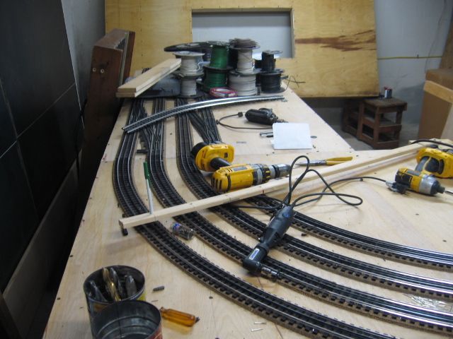
A slightly different approach.  We used a large compass, and kept the center rail in-line with the compass point, (ball point pen), as we continued to screw the track down every 3 to 4 inches.  Atlas track screws were used.

The initial pen lines were used to install cork roadbed.

Center point all curves.

Ball point pen on top of the center rail as screws are being installed.  You are also adjusting all ties as you work at fastening the piece of flex track.  Rail Ends are squared with a dremel cut-off at the end of each flex track section before the next section is installed.  Used/re-cycled, flex track was used for this project.  I tended to add wood ties as needed.

Works for radii, the template method, IMO, probably works better for curves that are not symmetric.

Have fun with your project.

Mike CT

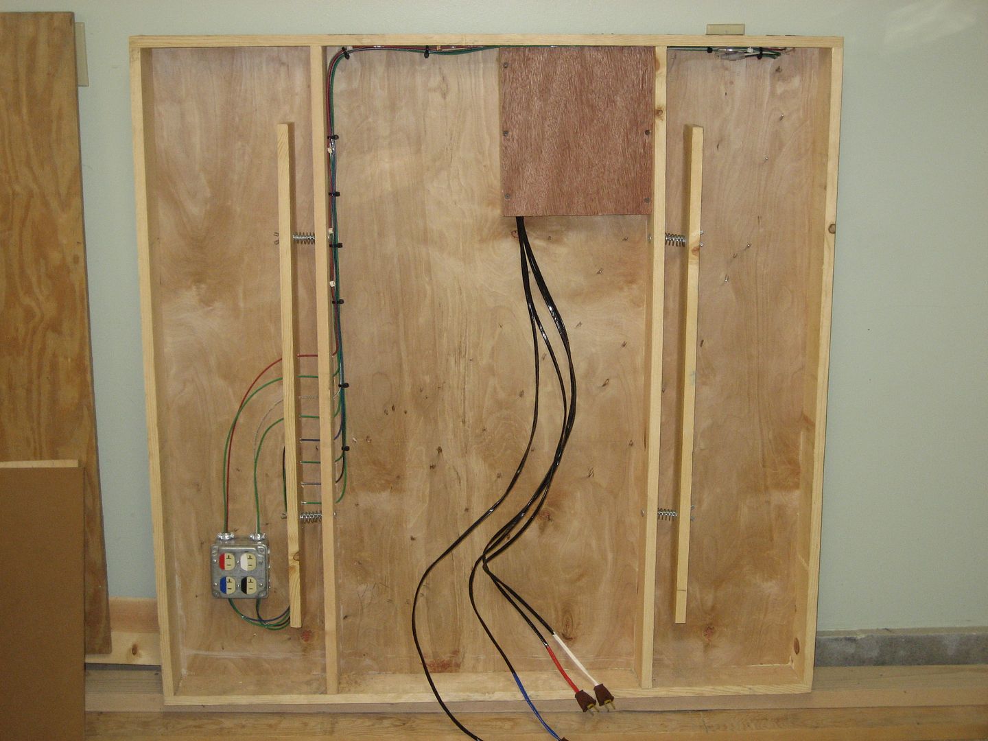
Modular wiring for one of the curved section modules.  There are (4) track circuits Red/White/Blue/Black.  Green is common color for all tracks.


Last edited by Mike CT

Buzz,

Great work both on the Jigs and pulling together such a nice post.

May I add one more jig suggestion to your collection.

A curve easement jig. 

Instead of abruptly transitioning from straight to full curvature, ease on into the curve! 

Start with a 10 inches of straight, then make a continuously changing curve that starts at something like a 0-200 (100 in radius) and smoothly transitions to O-72.  You can decide how rapid the change in curvature is.  My guess is going from O-200 to O-72 over a run of about a foot or so would be good.  Along the easement curve, mark where tangent points to curves are.  Eg O-120, O-112, O-104 etc.  That way you know how far to lay track along the easement before you start with your fixed curvature jigs. 


Like your jigs you would need one "innie" and one "outie".   But you need only two easement jigs!

Last edited by BillP

BILLP,  makes a great point about easements. The beauty of using flex track is to make your curves look less symetrical. Make the track go where you want it to go. Not where the compass tells it to. If you want your curves to look perfect. You may as well just buy sectional track. On an operation note. I run body mounted Kadee's. Even on passenger cars. On curves with an easement. No derailments even if the curve turns into an 072. Without them. Instant derailment coming off a straight portion into the curve. When I built mine 28 years ago. I made up a jig and would bend the Gargraves to roughly an 072 curve. From there Iwould place it on the layout and just tweak it to fit where I wanted to end up. I would just bend it back slightly to create an easement.

 If I were starting over today. I would use ROSS sectional track. If 072 was my minimum. I would start with say an 096. Then an 084 followed by my 072's to complete the curve. Use the same formula exiting the curve. It may not come out exactly where you want it to. Then use flex track to get it back on course. On the prototype. The terrain and surroundings dictated where the track went.

@tplee posted:

I use two sided jigs that I have made to make my track curves as smooth and consistent as possible.The jigs are made from 1/2" MDF.  Each jig has two radii for each curve radius that I will need. Those radii are 72", 80", 88", 96", 104", 112", 120". AS an Example for O-96" I made the top of the jig radius 46 15/16" and the bottom radius 49 1/16". They are 48" long, and close to 4" wide. The lessor radius is always on the top and the greater on the bottom. This arrangement allows me to bring the ties in contact with the jig from the outside, or the inside of the curve. The track ties can be brought into contact with bar grip clamps and fastened down as you proceed.


Jig Radii     Top (inside)    Bottom (Outside)

72"             34 15/16"       37 1/16"

80"             38 15/16"       41 1/16"

88"             42 15/16"       45 1/16"

96"             46 15/16"       49 1/16"

104"            50 15/16"       53 1/16"

112"            54 15/16"       57 1/16"

120"            58 15/16"       61 1/16"


The radius can be cut by following the circumference tool's drawn line as shown. Or if available use a Festool jig saw with the special curve cutting attachment.


If I am laying parallel tracks. I use an addition jig that will allow the appropriate inter-track clearance. Or, I use multiple, equal sized blocks, (6 to 8) every 3 or 4 ties off the original installed curve. This option allows easy installing of curves that are not the standard size radii. instead of 96" you might need 94 1/2" radius, which would require a set of 2 5/8" blocks between the 104" radius ties and the desired 94 1/2" radius curve vs the 1 7/8" for the 96"radius curve.


Group of Jigs

80" 88" 96" 104" 112" 120" and 72" (Not Shown)


Group of Jigs 80


Buzz,


What type of tool did you use to cut out the curved templates from the 1/2" MDF board?


Thanks,

Just rediscovered this thread - great info. 

Were you able to get an accurate cut just by using the jigsaw, or did you sand to the line or use a circle-cutting jig?

I remember talking with you at a meet in central Indiana regarding the plans for your layout.  Since this thread was started over 9 years ago, I'm wondering how the layout turned out.  Have you posted any pictures of it?

@Mallard4468 posted:

Just rediscovered this thread - great info.

Were you able to get an accurate cut just by using the jigsaw, or did you sand to the line or use a circle-cutting jig?

Im wondering the same thing, is there is some type of circle cutting attachment I can purchase for a jigsaw?  I tried cutting my templates out freehand using a jigsaw, but there are certainly a lot of imperfections doing it that way.

Last edited by Lionel16

However, I still feel the terms "easy" and "Gargraves flex track" are mutually exclusive.  I tried it once in the mid-80s, failed miserably, and vowed never to do it again.  Fortunately, when I got back into the hobby in 2002 or so, Gargraves and Ross had started to sell fixed curves.  I was off and running.

Actually, I found Gargraves flex to be easier to use than sectional track.  You have unlimited flexibility in laying the track, and if an O72 curve isn't quite right, it can be an O75 curve.   I did my entire layout with Gargraves and Ross.  I did use Ross O72 sectional curves for certain places where I knew I needed exactly O72.  However, I used three cases of Gargraves flex for most of the track.  It also mates perfectly with my Ross switches.

I used this Harbor Freight cutoff saw for most cutting, and the Dremel for the rest.  The HF cutoff saw was $30, I see it's back there again.

Attachments

Images (1)
  • mceclip0
Last edited by gunrunnerjohn

Add Reply

Post
The Track Planning and Layout Design Forum is sponsored by

AN OGR FORUM CHARTER SPONSOR
×
×
×
×
Link copied to your clipboard.
×
×