HC-SR04 Ultrasonic Sensor

Train Detection Block Signals

I thought I share the use of this ultrasonic sensor, I was able to utilize the sensor in my outdoor dead rail layout as a train/block detection on my layout.

Since converting the Baldy & Palms Railroad to “dead rail” in early 2021, the track detection circuit on the upper loop has been functioning correctly about 80% of the time.  The reed switch circuit would get triggered by the magnets at one end of the block and not at the other end.  This made the circuit go out of sync.  I decided to try several other sensors with the Arduino to find a suitable solution. I tried the current sensor, voltage sensor, relay circuit, and the IR sensor, none of these performed reliably.  
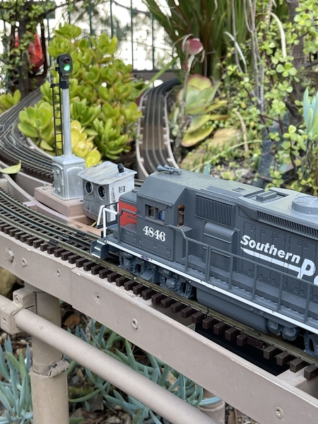
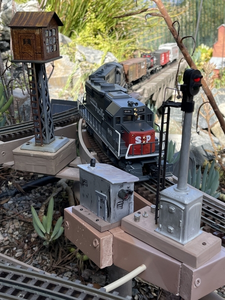
E5AAA3D6-6672-4723-A343-8FA647551FB3CC6447FA-7E70-465F-A3A1-868B85D6BD7A67884DD9-A5F2-4578-9331-ACD003FE76B0I discovered the HC-SR04 ultrasonic sensor and decided to experiment with this sensor.  I also created a better Arduino code with the HC-SR04 sensor.  I adapted the HC-SR04 sensor to fit in a small signal shed to match and blend with the block signal.  The Arduino code is written so the HC-SR04 monitors motion from about 4 to 8 CM across the track. When a train is detected on one end of the block, the signal will turn red, and remain red until the train exits the other end of the block, at which the signal will reset to a clear green signal.  This can be used with two or three aspect signals.  The code just needs a few lines of code activated. The circuit has performed very well, so I plan to incorporate this circuit in other trains detection blocks on the layout. Check out the YT video for the Arduino code sketch and circuit design.   YT Video - HC-SR04 Block Signal

Hope this post helps other outdoor layouts having the same problem and eliminate the need to put magnets on locomotives and rolling stock.

Attachments

Images (3)
  • E5AAA3D6-6672-4723-A343-8FA647551FB3: Approaching upper loop
  • CC6447FA-7E70-465F-A3A1-868B85D6BD7A: Exit upper loop
  • 67884DD9-A5F2-4578-9331-ACD003FE76B0: HC-SR04 sensor
Videos (1)
trim.349B1F13-F9FE-4C7B-B3ED-5CC63BAD6F68
Last edited by sjbuff
Original Post

Replies sorted oldest to newest

@sjbuff posted:

HC-SR02 Ultrasonic Sensor

...

Maybe a typo; I think it's the HC-SR04 (not 02).  For 78 cents (including shipping) I just bought one just to see what it is!  It may not get here for a couple months but oh well!

hc-sr04

If you have a datasheet or something with more technical specs than the typical eBay Asia website provides please post it...

Or a bit more from Amazon with presumably faster delivery...

a bit more on Amazon

Attachments

Images (2)
  • hc-sr04
  • a bit more on Amazon
Last edited by stan2004
@SteveH posted:

Ron, this appears to be a great solution for block detection, especially for an outdoor layout. Thank you for sharing.

Maybe a dumb question as I assume you would have designed it this way... Do your hardware configuration and sketch provide for block occupancy signalling if a train runs in either direction?

I'm curious, would that require you to know the direction the train is running in....how does that work?

@A. Wells Can you please rephrase you question, I don't understand what you're asking.

If my question was unclear, here's another way to ask it.  Since the sensors merely detect a series of 8 transmitted 40kHz pulses reflected back to itself from the train passing in front of it, the sensor itself would be unaware of which direction a train is passing.  The sketch would need to be written in such a way as to turn on the signals when a train enters the detection zone from either end, and off again when it exits.  I don't presently have the knowledge to understand what the sketch does exactly, but this is something I'm considering learning more about.

@SteveH posted:

@A. Wells Can you please rephrase you question, I don't understand what you're asking.

If my question was unclear, here's another way to ask it.  Since the sensors merely detect a series of 8 transmitted 40kHz pulses reflected back to itself from the train passing in front of it, the sensor itself would be unaware of which direction a train is passing.  The sketch would need to be written in such a way as to turn on the signals when a train enters the detection zone from either end, and off again when it exits.  I don't presently have the knowledge to understand what the sketch does exactly, but this is something I'm considering learning more about.

Oh, gotcha!  Like with my crossing gate set-up which requires 4 magic areas.  Two to detect the train entering the outer area from either direction and two to detect when trains leave the gate area.  (I'm still waiting on a magic refill from Mouser.)

I'm assuming I can get away with not having to detect the direction of the train.  However, if I'm going to need to get an estimate of speed, I might as well to report direction.

Last edited by A. Wells

SteveH  and other interested: 

I added the Arduino sketch, which you may use and tweak to fit your design.  Let me do my best to explain how the sketch works with the ultrasonic sensor.  When Arduino is first powered up, the two HC-RS04's are initiated to get their bearing.  The sensors are now pinging outward to a distance of about 100 centimeters.   Same time the block signal is defaulted to a clear GREEN signal.  As the Arduino code runs the loop of code, the code is looking for changes in the distance sensing of both HC-SR04's.  I have written the code so the HC-SR04's are looking for changes between 4 and 8 centimeters. Any object detected outside the parameters is ignored. Once either side of the block (either HC-SR04) detects a object within the trigger parameters, the code will initiate the code for the signal to change a occupied RED signal. 

Now the train has entered into the occupied block section. The signal will now remain in a occupied RED state until the train exits the other end of the block. I wrote the Arduino code to only switch case to  the default clear GREEN signal when the train exits the opposite end of the block. Since I'm using two aspect signals, I needed to transition mode from RED to GREEN, so I added a flashing red sequence for a few seconds until returning to default clear GREEN status.

The train can come from either direction to occupy the block, but in order to clear the block the train needs to exit the opposite side of the block.  Instead of the flashing red sequence, you could add a YELLOW signal for a few seconds before returning to default clear signal.  (This code is in the sketch, but is not active.)

What's happening when the train is in the occupied block, and has pasted one of the HC-SR04 sensors.  The exit sensor is waiting for a object trigger to move to the next case of beginning the default clear signal sequence.  Until the exit sensor is triggered, the block state will remain occupied RED state.

I am also working on a circuit with the HC-SR04 for a grade crossing activation.  With pretty much the same code principals.  They're a bunch of things you can do with this circuit, tie the sensor to a station announcement for instance, or sawmill sounds when approaching a lumber mill siding.  All this is done through the Arduino and a sound board and is activates the animation when a train rolls by.

I hope this explains how I'm using the HC-SR04 to detect trains.  I found this to be good solution to my outdoor o scale layout.  I went with this method, because I did not want to rely on the track continuity to maintain the circuit state.  This way, once the senor is triggered, the state remains same until another trigger and a change of state.

Attachments

This is "other interested".  Do you have any issues with false leave detections  when the open areas between cars pass in front the sensors?  Have you considered using a comparator IC with low and high values (hysteresis) and pots to trigger a signal into the Arduino?  This would make it easier to adjust on the fly instead of having to recompile the code.

Other Interested

What amazes me (I watched your video) is how you methodically experimented with various technologies - optical, magnetic, electrical, and finally acoustic - to arrive at a solution.

My 78-cent free-shipping (!) acoustic module won't get here for months if at all but what I want to see if it's practical for the average OGR reader to apply this.  By that, I think most guys think of the 153IR ($45.99 MSRP) as the standard for occupancy detection when insulated-rail is not an option.  You simply position the 153IR next to the track, apply AC Accessory power, and hook the controlled accessory (signal, crossing gate, whatever) directly to some screw-terminals.  No soldering, no programming, no fuss, no muss!

Remember folks, OGR is a discussion forum and we're in the Electrical section.  So I may be talking to an audience of 1 (myself) but oh well!

In reviewing the datasheet, what's needed is a periodic pulse to trigger the module to send out an acoustic pulse.  This might occur, say, 10 times per second.  The module looks for an echo from the inaudible (ultrasonic) burst hitting a passing train in which case it generates an "echo detected" pulse.  The elapsed time (measured in a fraction of a second) from trigger to echo indicates how far the target is.  A building or other scenery structure on the other side of the track will generate an echo so the "trick" is to measure time to the echo and discriminate (ignore) reflections that come from distant objects (vs. a passing train).  All this indeed takes advantage of the "power" of an Arduino.

What I'm pondering is if it's practical and cost-effective to cobble together a circuit that embeds this 78-cent module into a, say, $5-10 DIY module that emulates a 153IR...without an Arduino.  While the Arduino and the like have been a godsend to the O-gauge community, it can be a daunting endeavor to the average OGR reader.  Likewise, there are many who find soldering or working at the component-level a show-stopper.  I get that.

Last edited by stan2004
@stan2004 posted:
What I'm pondering is if it's practical and cost-effective to cobble together a circuit that embeds this 78-cent module into a, say, $5-10 DIY module that emulates a 153IR...without an Arduino.  While the Arduino and the like have been a godsend to the O-gauge community, it can be a daunting endeavor to the average OGR reader.  Likewise, there are many who find soldering or working at the component-level a show-stopper.  I get that.

It's obviously possible, but I don't know if you'll hit that price target.

This statement in the data sheet is a bit confusing.

When tested objects, the range of area is not less than 0.5 square meters
and the plane requests as smooth as possible, otherwise ,it will affect the
results of measuring.

I hope that doesn't mean they expect that large an object to range on, we'll have to go to bigger engines!

Thanks all, remember my main issue was to get a sensor to function in the outdoor ambient light of sunshine and shadows throughout the day.  Also I am running dead rail, so there is zero track voltage as well.  I tried the 153IR, but did not get reliable results.  The HC-SR04 has been error free since I installed.  I am quite impressed.  I agree for most OGR reader and railroaders, the IR sensor, voltage and current sensors would probably work just fine indoors.   Many in the G scale layout use the reed switch and magnet circuit, but I found this to be not 100%.  I did use this method for awhile until I found this ultrasonic sensor.

I have been fiddling with the Arduino for awhile now, and YES the code and understanding of coding and circuit can be intimidating for many.  I've spend a lot of time learning the code and building circuits, which I enjoy.  Now to apply this to my layout is what I'm working to achieve.  Plans for other circuits are also in the works.

Attachments

Images (1)
  • HC-SR04_block_detection_circuit: Tinkercad circuit

For those who might be interested, here's avideo on the HC-SR04 from YouTube. It's 48 minutes long but fairly comprehensive. It shows how to use the Arduino with this device and provides code to program the sensor in raw form as well as how to program it with a library.

He concentrates somewhat on getting accurate readings for distance measurements including using a temperature and humidity sensor to calculate the speed of sound with more precision.

I realize that this amount of accuracy is not pertinent to this application, but you might imagine being able to differentiate between two trains on parallel tracks.

It’s all in the code, I’m pretty sure code can be written to sense different distance. My code looks for objects within 4 and 8cm. Adding code to sense a different area should be doable. Within the range of the sensor. This will be something I can experiment with.  The video from the Dronebot Workshop is very comprehensive and worth the watch for those seeking more information on this sensor.

...

This statement in the data sheet is a bit confusing.

When tested objects, the range of area is not less than 0.5 square meters
and the plane requests as smooth as possible, otherwise ,it will affect the
results of measuring.

Yup.  That's why I wanted to mess with one.  I'm thinking the 0.5 sq. meter "range of area" is suggesting you don't want interfering clutter that can create false reflections.  Or maybe it means you don't want a separate HC-SR04 within that range because of interference.  The smoothness might be implying the target should be a flat surface perpendicular to the acoustic burst for better reflection.

I see this as part-and-parcel of learning about this "technology."  That is, with the IR technology we've learned how ambient lighting (especially sunlight) can interfere with operation.  Likewise, the IR reflections are better when the passing train is white or lightly colored rather than black or dark.

Last edited by stan2004

@SteveH - This goes back to one of your early comments regarding detecting train direction and block occupation detection.  There is a scenario where you can make a block think it's empty (when it's actually not) by reversing the consist while it's over the "last" detector.  However, I think for most people this isn't necessary and just a matter of pedantics.  For a crossing gate though, it might be a necessity.

Anthony

Sure you can.  The block has signals on both ends, when either sensor is triggered, the blocks is turns RED.  Take it, in my scenario - trains roll through the block, there is no need to stop in the block and reverse back from the entering sensor.  Which if the train did reverse the train back out, the sensor would still remain RED, because the code is waiting for a trigger on the other end of the block.  Yeah a train could roll into the block from the other end, past the RED and trigger the CLEAR sequence.

But this scenario would not always play out, I'd lose my model railroading engineers certificate blowing by a RED signal. haha 😊

My next project is a crossing gate circuit, which has the same theory in mind, a trigger to active crossing gates when train approaches and another trigger when train exits the crossing gate area.  The Arduino code is where all the animation can be controlled.

@sjbuff posted:

Sure you can.  The block has signals on both ends, when either sensor is triggered, the blocks is turns RED.  Take it, in my scenario - trains roll through the block, there is no need to stop in the block and reverse back from the entering sensor.  Which if the train did reverse the train back out, the sensor would still remain RED, because the code is waiting for a trigger on the other end of the block.  Yeah a train could roll into the block from the other end, past the RED and trigger the CLEAR sequence.

But this scenario would not always play out, I'd lose my model railroading engineers certificate blowing by a RED signal. haha 😊

My next project is a crossing gate circuit, which has the same theory in mind, a trigger to active crossing gates when train approaches and another trigger when train exits the crossing gate area.  The Arduino code is where all the animation can be controlled.

I'm curious if you saw my topic on Crossing Gate Regulations from last week?  I want to try to make it as close to real life as possible.  I didn't want the gates to come down right when the train is on top of the crossing.  This wouldn't be good for my tractor trailers.

A. Wells. /No I did not, I’ll go check out your post. My thought is to have the sensor, say 3 feet away from crossing on both sides , and trigger lights and gates to the approaching train, and clear when other sensor detects the train has pasted. Returning gate up and stopping the flashing lights.  I also thought of placing a flashing amber light as the default state, then I know the circuit is working. I’ve seen European crossings with a slow flashing amber light when crossing is clear and moves to flashing red when a train is approaching.  I know not prototypical for US crossings, but it’s cool to see the crossing always active.

I received my 78 cent HC-SR04 and designed a circuit to make it work like the Lionel 153IR or MTH Scaletrax ITAD.

HC-SR04 proof of concept - january 2022

That is, you supply AC Accessory voltage.  You position the occupancy detector on the side of a track.  You hook up the controlled accessory to the relay outputs.  You set the sensitivity/range ... for example to detect a engine across a 2nd distant parallel track.  You set the time delay to keep relay on after train passes.

It works swimmingly and could be done for $5 in jelly-bean components for a well-stocked DIY'er.  My out-of-pocket was just the 78 cents for the sensor module.  I don't recommend you try this at home since it is a lot of component-level assembly and such.  I show the 153IR and ITAD by way of "size" comparison to show the circuit could fit in a trackside cabinet albeit there would be some work to custom-fabricate a housing maybe requiring a 3-D printer or whatever.

But if anyone is truly interested in how I did it, I can elaborate my observations and thinking.

This is a very interesting module which is very widely available and very widely used especially in hobbyist and robotics applications.  Just google HC-SR04 and you will be overwhelmed!

Thank you @sjbuff for introducing this technology to the forum!

Attachments

Images (1)
  • HC-SR04 proof of concept - january 2022
@stan2004 posted:

I received my 78 cent HC-SR04 and designed a circuit to make it work like the Lionel 153IR or MTH Scaletrax ITAD.

That is, you supply AC Accessory voltage.  You position the occupancy detector on the side of a track.  You hook up the controlled accessory to the relay outputs.  You set the sensitivity/range ... for example to detect a engine across a 2nd distant parallel track.  You set the time delay to keep relay on after train passes.

It works swimmingly and could be done for $5 in jelly-bean components for a well-stocked DIY'er.  My out-of-pocket was just the 78 cents for the sensor module.  I don't recommend you try this at home since it is a lot of component-level assembly and such.  I show the 153IR and ITAD by way of "size" comparison to show the circuit could fit in a trackside cabinet albeit there would be some work to custom-fabricate a housing maybe requiring a 3-D printer or whatever.

But if anyone is truly interested in how I did it, I can elaborate my observations and thinking.

This is a very interesting module which is very widely available and very widely used especially in hobbyist and robotics applications.  Just google HC-SR04 and you will be overwhelmed!

Thank you @sjbuff for introducing this technology to the forum!

Stan, can I get the schematic and BOM for this?  I'll create and post a PCB that will make assembly practical for a wider audience if they don't have to do a lot of wiring.

hc-sr04 proof of concept

Image should be expandable.

Here's the theory of operation.  Reviewing the HC-SR04 datasheet first will help.

Timer1, a 555 timer IC generates short pulses 10 times per second to trigger the HC-SR04 to send an ultrasonic burst.  This is the TRIG signal to the HC-SR04.  The HC-SR04 then generates a pulse output whose width is proportional to the distance to the target.  This is the ECHO signal and is a pulse stream at the 10 times per second rate.  The ECHO pulse width translates to 17cm/msec.  So if ECHO signal is 1 msec wide, the target is 17cm away.  If ECHO signal is 2msec, the target is 34cm.  Practically speaking, if positioned on the side of a track, a typical target (passing train) distance would be 5cm away so we're looking for pulse widths around 5cm/17cm x 1 msec = 0.3msec or 300 usec.

Timer2, half of a 74HC123 dual-monostable timer, generates an adjustable pulse width corresponding to the desired sensitivity or range of the sensor.  Since the sensor has a purported range of several meters, it will always be getting an echo from some part of the layout beyond the tracks.  In other words, the ECHO pulse width must be tested to find SHORT pulses meaning the target is only, say, 5-15cm distant.  The test will be to look for ECHO pulse width which are narrower than 300usec (5cm) - 900usec (15cm).  So Timer2 uses a trimpot to generate an adjustable pulse width that covers this range.

Timer3, the other half of the dual 74HC123 does the timing discrimination.  It compares the ECHO signal pulse width to the reference pulse width and if the ECHO is narrower than the desired target distance, it then generates a long pulse that turns on the SPDT relay.  The long pulse is settable in seconds just like the 153IR or ITAD.

It's that simple!  I show in the red circle what an Arduino or microcontroller could do.  You'd still need some kind of power supply to convert Accessory AC to 5V DC that the Arduino needs.  You'd still need some trimpots or method to adjust the distance-to-target sensitivity and the relay delay time.  And you'd still need some buffer to drive the SPDT relay.

Parts list attached.  The only non-jelly-bean (garden-variety) part is the relay.  The HK4100F is widely available and has 3 Amp contacts so plenty for a 153IR/ITAD type application.  Datasheet attached. 

Some effort was made to minimize the number of unique parts.  If your parts cupboard is bare and you're trying to build 1 or 2 to mess with, it will be oh so frustrating since minimum quantities, shipping, etc. will drive the cost thru the roof. 

Again, this is just a proof-of-concept.  I make no claims that this is better, worse, or whatever than any of our existing occupancy detection methods.  I suppose this would most likely be compared to the 153IR/ITAD Infrared methods.  In that regard, I'd think the occasionally reported issues/problems detecting IR/optical reflections off dark-colored surfaces would not be a factor for acoustic reflections.

OTOH, I only got 1 module to mess with, but I'm thinking there may be issues trying to use two or more of these in close proximity.  That is, the HC-SR04 sensor range is claimed to be several meters

Attachments

Not a dumb question at all.  The 5V circuit uses about 10mA when idle and waiting for a train.  Then about 50mA when the relay turns on.  With 14V/18V AC input:

When idle, 7805 input is about 19/23V DC.  So TO-220 dissipation is about 140/180mW; so that's no problem.

When active, 7805 input is about 16/20V DC.  So TO-220 dissipation is about 550/750mW; so yes, it does get a bit toasty but within spec.  So yes, I suppose you wouldn't want to mount the 7805 against a plastic wall or whatever.  Note that the 7805 input voltage drops when relay turns on because "only" half-wave rectification is used.

Believe it or not I thought about that - in trying to minimize the number of different components, you'll see there is another 220uF in the circuit.  220uF worked out well since it is not large enough to maintain the half-wave rectified DC level when the relay turns on and droops about 3V DC or so reducing the TO-220 dissipation by 150mW or so.  Every little bit helps!

Wow!  If you're really considering making a PCB design, keep me in the loop and post stuff here.  I'm sure I'll have comments.  I'd think the biggest stumbling block will be finding/making an enclosure.  The 2 trimpots have to be cleverly positioned for screwdriver access...though these tend to be one-and-done adjustments for a given layout.

Stan, thank you very much for drawing the schematic and posting it here.  Have you done any testing to find out how well the detection works with rounded objects (like tank cars and steam boilers)?

Also, curious about its ability to either detect and/or discriminate between the presence of trains on two or more parallel tracks, if the detector is either placed close to the first track or some distance further away from the parallel tracks.

For example, if attempting to use the detector to activate grade crossing signals for 2 or 3 parallel tracks, would one detector sense the presence of passing trains on any of those tracks and activate the signalling circuit if placed at a sufficient distance from the tracks?

As an opposing example, if the detector were placed close to to a mainline track for detection of a train heading into this mainline grade crossing, but there is also another nearby diverging spur track on the far side ~ 6" away from the closer detected track that doesn't cross the auto road, could a train on the spur be ignored by the detector?

@stan2004 posted:
Wow!  If you're really considering making a PCB design, keep me in the loop and post stuff here.  I'm sure I'll have comments.  I'd think the biggest stumbling block will be finding/making an enclosure.  The 2 trimpots have to be cleverly positioned for screwdriver access...though these tend to be one-and-done adjustments for a given layout.

Stan, you will most certainly be in the loop!  I'm entering the schematic into DipTrace now, and then I'll do a trial fit to see what size PCB will work.  Since I don't have that relay, and I already got bit by low current contacts, I'll be using the Songle 5V relay with 10A contacts.  I may have to improve the 5V supply.

That was fast!

1. Bridge is rotated.  AC inputs are going to the + and - terminals of the bridge.

2. Output of 1st 74HC123 should be pin 13 Q (not Q*).

And how about humoring me and plopping down the pads for the HK4100 relay.  I figure I'll be building one and presumably this shouldn't change the board size which I figure is what drives the raw PCB cost.  I guess you would need to build the part for your library.  In other words, just add a 2nd relay in parallel and the builder can decide which to install.  Note that the HK4100F is the relay used in the Lionel 153IR.

hk4100f alternate

Attachments

Images (1)
  • hk4100f alternate

OK, I noticed that not only was the bridge rotated, but I also left a surface mount part in the design.  But I didn't pick up that I used the wrong output on the HC123, good catch.

I'll have to look at putting in the pads for the HK4100 relay, given the large traces for the 10A model, that could be interesting fitting it in.  I didn't initially consider it as I also didn't have any of them on hand, and the only place I saw them was overseas with weeks of delay.

@stan2004 , I notice that there are two different pinout diagrams in the data sheet for the HK4100F, and they don't have any identification as to which matches what part number.  Which one of these is the "right" pinout?  Truthfully, I can't imagine why they needed two totally different base pinouts for the same specification part...

I'm "assuming" that the first one is the HK4100F and the second one is the HK4101F, but since there is no labeling of any kind on the two sets of base diagrams, I'm not 100% sure that assumption is correct.


This is the datasheet for the relay that I have: HK4100F-HUIKE.pdf

Attachments

Images (2)
  • mceclip0
  • mceclip1
Files (1)

Stan and John:

I'm glad that my suggestion on using a HC-SR04 in the model train world is a good idea.  I like how you're looking at ways to use this sensor without the Arduino.  Making a straight circuit with simple distance adjustments can make this sensor even easier to use.  Hats off to you both.  I'm working on a grade crossing circuit, which I'll post once I have finalized the code and sketch.  Thanks again from all us model railroaders. 😊🚂

Add Reply

Post

OGR Publishing, Inc., 1310 Eastside Centre Ct, Ste 6, Mountain Home, AR 72653
800-980-OGRR (6477)
www.ogaugerr.com

×
×
×
×
Link copied to your clipboard.
×
×