1. I think I may have figured that out, it requires a little hand routing to make it work.

2. There's only two IC's, I had oriented them to facilitate routing, so I rotated one with no issues.

3. The 3362P is twice the price of the the 3306F I'm using.


4. With a heatsink, the 7805T does the trick.  I just moved it to the edge of the board where it could easily accommodate a heatsink.

5. They're labeled on the back, not any room to put the labels on top.

Attachments

Images (2)
  • mceclip0
  • mceclip1

1. I think I may have figured that out, it requires a little hand routing to make it work.

2. There's only two IC's, I had oriented them to facilitate routing, so I rotated one with no issues.

3. The 3362P is twice the price of the the 3306F I'm using.

4. With a heatsink, the 7805T does the trick.  I just moved it to the edge of the board where it could easily accommodate a heatsink.

5. They're labeled on the back, not any room to put the labels on top.

1. Now I'm a happy camper!

2. And you chose wisely...that is, now the DIP ICs even align with the DIP bridge!

3. Yes, but by my reckoning, the #1 failure mode on the 153IR occupancy detector is the open-frame trimpot.  With some shopping around, the 3362P is reasonably priced (20 cents each) in small quantity like at lcsc.com:

3362p-1-204

Not asking for a modified schematic to show both parts in parallel or anything fancy!  I figure it costs you nothing to add 2 vias or holes...if only to shut me up!  

mceclip1

4. Yup.

5. Yup.

Attachments

Images (2)
  • 3362p-1-204
  • mceclip1
@stan2004 posted:

May be optical illusion but is the left-to-right distance 0.1"/2.54mm"...looks like the added holes need to move right just a tad.

Yeah, the 3362P is 2.54mm grid whilst 3306F is 2.50mm grid but I'll take what I can get.

Picky...picky...picky... Yep, I screwed up the measurement, shouldn't calculate displacements in my head.

Attachments

Images (1)
  • mceclip0

I couldn't quite overlay the relays completely, in order to get clearance between the leads the smaller one wouldn't quite fit in the footprint of the big one.  I got close...

The first time I did this, the autorouter couldn't handle it, so I manually routed the relay contacts.  I moved them several times slightly shifting things, and the last time the autorouter managed to do the complete route without help.

I also shifted the regulator over a bit to allow a little more room to install a heatsink.  I normally just whack one out of aluminum sheet if I need it.

@stan2004 posted:

Separately, did you confirm clearance from bottom of J1 to U2.  The J1 silkscreen outline looks a bit small for a "real" screw-terminal block.  That looks like a smaller square-pin header outline?

The two pin 3.5mm terminal blocks fit on both of the connector positions, I just checked them.  I'm using 3.5mm Euro-style connector blocks.

Attachments

Images (1)
  • mceclip0

Hi Dennis, hope you are well.  These detectors really do work very well. Not sure how many others have them in operation (other than the OP), but I have two working on the layout now, and love them. Several more are in the planning stage. And this got me back into 3D printing in a big way.

I plan to put the .stl files for the cabinets and bases in the 3D repository, but not sure what category they ought to go into. Can you advise?

Rod

Last edited by Rod Stewart

The two pin 3.5mm terminal blocks fit on both of the connector positions, I just checked them. ....

Got it.  I guess the 3D photo would have showed the clearance; it's just that in an earlier 3D photo the terminal block hangs over the end of the board such that the silkscreen does not actually match the footprint.

That said, it then seems you could fit top-of-board silkscreen lettering of NO C NC between the relay outlines and J2?

Rod,  Beautiful work... and, thank you, for your generosity!  If you can remember how to login... you have your own folder ...drop it in there.  If you can't remember you can just email it to me and I'll take it from there.  In either case I have to place it in the catalog anyway and bump (update) the thread so folks know it's available.  Hmm... category .... I suppose Signals & Signs.

Last edited by Dennis-LaRock
@stan2004 posted:

Got it.  I guess the 3D photo would have showed the clearance; it's just that in an earlier 3D photo the terminal block hangs over the end of the board such that the silkscreen does not actually match the footprint.

That said, it then seems you could fit top-of-board silkscreen lettering of NO C NC between the relay outlines and J2?

I could put it there, but it would be covered up by the terminal block, however I stuck them in.  They're visible with that terminal strip model.  I don't have a 3D model for the euro-style strips I use, they would cover the labels.  The terminals I use come to the edge of the board, but don't hang over.

I also show it with your preferred small relay.

Attachments

Images (2)
  • mceclip0
  • mceclip1

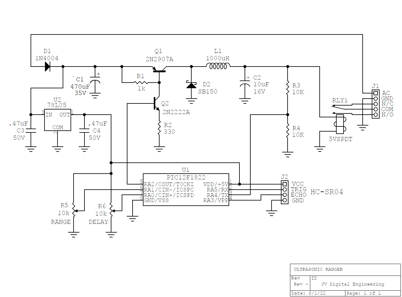
The PIC is "in the loop" stepping down the DC and hence needs a 5V reference voltage which is supplied by the 78L05.  The neat thing is once the relay is closed, the PIC can step down the relay coil power to a fraction of the power to initially close the relay...this for the case of train stopping in front of sensor forever.

My first pass included a .1" border, but I squeezed to 1.8" wide with a .05" border.  I assumed the sensor would be plugged vertically into the board, so there is free area on both sides of the sensor connector that eats up .2" in that dimension.  Of course that can be eliminated with a 90 degree connector with the sensor hanging off the end as it would have to be with your layout.  The relay, terminal block (.381 spacing), and trimmers dominate the board area.  The sensor itself is 1.8" long, so that dictates the width.

Here is version the version 1.0 layout.  Size is 1.8" wide by 1.5" high.  There is room for mounting holes in the bottom corners.  There may be some minor changes as I "apple polish" the routing.  If there is sufficient interest I'll order a small batch of PCBs.

UltrasonicRangerPCB_10

A connector can be used for J2 so the sensor can be plugged in or the sensor can be soldered directly to the PCB.

Attachments

Images (1)
  • UltrasonicRangerPCB_10

Add Reply

Post
×
×
×
×
Link copied to your clipboard.
×
×