Stan did the heavy lifting on this one Ron. ![]() I'm just making it into a PCB so it'll be easy for other folks to duplicate. I do like the idea of doing this with hardware, even though I do have a lot of uP based products.
I'm just making it into a PCB so it'll be easy for other folks to duplicate. I do like the idea of doing this with hardware, even though I do have a lot of uP based products.
@gunrunnerjohn posted:@stan2004 , I notice that there are two different pinout diagrams in the data sheet for the HK4100F, and they don't have any identification as to which matches what part number. Which one of these is the "right" pinout? Truthfully, I can't imagine why they needed two totally different base pinouts for the same specification part...
I see what you mean. I'm after the 6-pin version. The 2nd diagram (which I too assume is the HK4101F) has only 5-pins; and if you google HK4101F, pics show it to be 5-pin so I think that clinches it.
Attachments
@SteveH posted:... Have you done any testing to find out how well the detection works with rounded objects (like tank cars and steam boilers)?
Also, curious about its ability to either detect and/or discriminate between the presence of trains on two or more parallel tracks, if the detector is either placed close to the first track or some distance further away from the parallel tracks.
For example, if attempting to use the detector to activate grade crossing signals for 2 or 3 parallel tracks, would one detector sense the presence of passing trains on any of those tracks and activate the signalling circuit if placed at a sufficient distance from the tracks?
As an opposing example, if the detector were placed close to to a mainline track for detection of a train heading into this mainline grade crossing, but there is also another nearby diverging spur track on the far side ~ 6" away from the closer detected track that doesn't cross the auto road, could a train on the spur be ignored by the detector?
Haven't forgotten about you! I figured I'd first attend to GRJ's efforts since getting a PCB would really move the ball down the field!
No, I have only done bench testing so that I could have all manners of instrumentation handy. I have found the most useful tool at this proof-of-concept stage is the oscilloscope since I can watch each and every ECHO pulse and see how it changes in real-time as objects come in and out of reflection range. But I just placed a Hudson boiler, a tennis ball can, and a coffee cup, with the sensitivity trimpot set to look for targets ~10 cm or less and they all tripped the detector within 1 cm of what a flat surface did.
I think it's the notion of setting the sensitivity as X cm or less that is novel. That is, with the speed-of-sound it is practical to measure "time-of-flight" since the ECHO pulse width changes about 60 microseconds per cm. Obviously trying to measure time-of-flight for the infrared method means measuring the speed-of-light which would not be practical! As an aside, I suspect the next sensor idea might be an optical sensor that uses "auto-focus" like technology to estimate distance to objects.
Anyway, if parallel O-gauge tracks are, say, 10 cm apart (600 microseconds change in ECHO pulse width) it is not hard to imagine this amount of timing change can indeed be reliably discriminated. I don't know if there's any application for this, but the "X cm or less" sensitivity setting means if you have 2 or more parallel track, this ultrasonic method can be reliably set to only trigger on the closest track (or the two closest tracks) and ignore anything further away.
As mentioned, the big unknown is the ability to use 2 or more of these in close proximity since the ultrasonic bursts are just sound waves and sound scatters rather well in air - unlike optical beams which stay in their lane. Of course a downside of the ultrasonic method is it would NOT work in a vacuum whereas the optical method would! ![]()
I guess all that can be said so far is it's early days and we're trying to catch up to @sjbuff and his ground-breaking work! ![]()
GRJ, I did not see the part number of the trimpot but wanted to confirm it increase R with CW turn? Measure-twice, solder-once!
Also, it looks like the 1uF capacitor after the 7805 disappeared? I'd like some "bulk" capacitance on the 5V supply line near or midway between the timing IC chips even if your 3-pin regulator a small cap on the output side.
Stan, good call on the pots, I'll check again and make sure the rotation is correct. One final thing I have to do is create a BOM once we think the design is laying flat.
As for the power supply, I used my switcher, but the same holes and pinout fit the LM7805. There's room for that with an optional heatsink if so desired, so I think we have all bases covered.
I added two .1uf caps right across the two chips, my chosen method of bypass in most cases. I got the second relay component mapped out and configured on the board. I was having trouble putting it on top of the other one, so I just stuck it beside it.
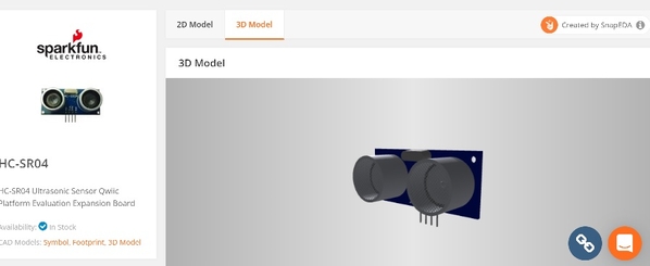
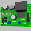
I'll make sure about the pot connections and then post all the files again. Here's a teaser of the 3D view as it stands now. This should be as it looks completed, the wiring of the pots shouldn't change anything about positioning. Too bad I didn't have a 3D model of the HC-SR04 to complete the picture... ![]()
Once we like the total design, I'll order some PCB's.

Attachments
Here we go, hopefully the "final" Rev 1.0 cut. I fixed the pots, they were backwards as predicted. I also added the mounting holes.
Ultrasonic Train Detector Schematic.pdf
Attachments
@stan2004 posted:
Stan, I could certainly look into some mounting holes, totally forgot about that option. As for the 3D models, it has to be in a format that DipTrace imports. The 3D modeling aspect is something I haven't spent a lot of time on as most of the stuff I do I can create a suitable model from existing parts.
Take a close look at the schematic if you will and make sure we're all laying flat there. I'll make any other changes we need and put some holes in the corners for mounting posts.
Schematic looks good. ![]()
In that case, I'll look into a PCB order, I think we have all the other bases covered. ![]()
Stan, Thank you for answering my questions about range and adjacent tracks discrimination. John, thank you for working up the PCB layout.
Maybe something else to consider. I'm wondering about the scenario of using this module for crossing gates and the benefit of having two detectors, one on each side of the grade crossing for trains approaching from either direction.
Also there is the notion of using this for block detection and having one or more additional detectors within and at the other end of the block.
Would it be possible to provide one or more inputs just prior to the relay trigger so that outputs of multiple modules could be wired together to activate the relay? I see some advantages to this approach vs. just wiring the relay outputs from multiple modules together.
This may or course require a buffer between the Q2 output and the junction of D3 and the Relay coil.
Thoughts?
I actually thought about doing a slave link and firing all the sensors selectively. You'd have to do this somewhat intelligently so that any "sound" from other detectors would have dissipated. That's way in the future, let's get one working and tinker with it. ![]()
GRJ, are you posting this to OSH Park common area? It looks like about 4 sq. inches? That would be $20 ($5/sq. in.) for 3 boards. I will front the cost and order them and send you 1 (via NONMACHINABLE first class! LOL).
Stan, I'm ordering this from JLCPCB as it's six square inches and $30. The whole order of 30 boards shipped DHL is $57, much easier to digest than $30 for three! I'll send you some boards when I get them. If you have a hankering to order some from OSHPark, here's the Gerber files.
HC-SR04 Ultrasonic Train Detector Gerber.zip
Attachments
What are you going to do with 30 boards? ![]()
I realize that's "only" $2/board but I really think just a few boards, even if $30 at Osh Park for 6 sq. inches, will help to get our arms around the packaging. I really think the enclosure will be a stumbling block and should/will drive the board layout. Again, I will gladly pay the $30 ($10/board) and send you 1 to mess with...
Well, the order is in, Since the DHL shipping was the lion's share of the order, I just bumped it from ten to thirty. ![]() Too late to make a change on this one.
Too late to make a change on this one. ![]()
I also wanted 2oz copper for the relay traces, and with OSHPark you have to go to the thin board for that option. This isn't a candidate for thin boards, at least IMO.
OK. I'll just send you the $30 I would have sent to OshPark. Does your profile "display email" address take paypal? Or send me an email (you know my email address) from a valid email...
Stan, I'll let you know when I get them, it'll doubtless be a week or two. They quote 5 days processing and 3-5 days shipping. My experience has been it's at least that long and usually a few days longer.
@SteveH posted:...
Maybe something else to consider. I'm wondering about the scenario of using this module for crossing gates and the benefit of having two detectors, one on each side of the grade crossing for trains approaching from either direction.
...
Thoughts?
So my thoughts are:
1. The 5-wire crossing gate.
As you describe there is an application where either detector should trigger a crossing gate. And if the crossing gate is the 5-wire style, you can't simply parallel the NO and NC relay outputs as they would fight each other if only one detector is triggered. So the "standard" answer is an external arbitration relay. And since this can be done for around $5 DIY (like above) or $10 with an off-the-shelf relay, I too thought about this but want to focus on the detection sensing technology.
So yes, some kind of "party-line" connection could be made between 2 or more detectors so that if ANY detector is active then a chosen relay would trigger.
AFAIK, the latest Lionel incarnation of the crossing gates has only 3-wires. This only requires a connection to the relay NO of the detector...and all the NO contacts can be paralleled without an external arbitration relay.
2. Judicious choice of the "DELAY" time.
The 153IR and MTH ITAD detectors have the Delay adjustment to keep the relay triggered 10 seconds or more after the detected object passes. The DELAY gives the consist time to reach the other detector. Obviously you could stop the consist right on the crossing with the caboose 1" beyond the detector and the gates would go up. Well, don't do that! ![]()
3. Latching detector.
Can't recall if it was the current thread but the idea of the gates going down when, say, the East side detector is triggered...but then don't go back up until the West side detector is cleared. That is, if you have just an engine it is likely the engine will be between the two detectors for some interval during which the gates go up. So perhaps a mode where the relay latches when either detector triggers, and then unlatches only after the other detector is triggered and cleared. And this should support bi-directional travel. Well, this design obviously doesn't support this. I suppose a basic latching mechanism as described could get "fooled" if a consist trips the East detector...stops...and then backs up never reaching the West detector at all. In which case maybe the DELAY timer comes into play to release the gates after some settable time interval.
---------
Anyway, just wanted to jot down my thoughts. Yes, the tried-and-true insulated-rail method does not have any of these issues...but then again this is more fun discussing new ideas in our hobby! ![]()
Attachments
My vision was once the east trigger activated the gate crossing, the crossing gates lower and lights would flash until the next phase is triggered by west sensor. At this point the gate would not default to clear until the west trigger sensor completes its process. I know in the Arduino code I use a command called (switch case) where each case is a particular event. When one event begins ( lights and gates activated ) the microprocessor will continue to loop back in the code to look at all the possible switch case options and pending the input of the HC-SR04's the switch case would advance to the next option. Using a relay to trigger NO or NC, I'm not sure you can get the same results as switch case scenario. A calculated delay would be needed when switching the relay.
I am really looking forward on the prototype, and seeing what becomes of this circuit. Fantastic job you guys, running with this.. 👍
Well it was a bit awkward to set up but here's a scope video showing what I consider to be surprisingly stable and reliable ECHO pulse timing. In other words, I believe what I'm seeing.
The scope is displaying 10 pulses per second. It takes a while to appreciate what is going on here! This is measuring distance in real-time.
I'm wondering if there are other O-gauge applications that could benefit from the ability to reliably measure distance to an object - perhaps for some TBD animated accessory?
That is really cool! 👍 Yes to measure in real time. I was also thinking to sense a train coming into a station for example and have a station announcement be triggered. Or when a train out of view has cleared a particular area, trigger a location icon on a control panel, there's a bunch of things that this circuit could be used for.
That's impressive Stan, it really ranges pretty accurately and stable as well!
On the question of 40kHz interference amongst multiple HC-SR04 units, John's idea of a detector link that would stagger the transmitted pulse outputs among multiple units is intriguing.
Another alternative would be in the physical realm. There are a multitude of inexpensive porous acoustic absorbers which should be effective in this frequency range. For example, mineral wool, natural fabrics, etc. At this frequency, it should require little material thickness to effectively adsorb the propagated signal and prevent nearby detectors from interfering with each other.
Stan, would you be interested in seeing if this theory is applicable by placing something like a couple of layers of denim between the detector and another reflective object to see if the signal is adsorbed?
OK. I'm game for a snipe hunt! ![]()
So if I place 1 or 2 layers of denim (from a pair of jeans) in front of sensor, it simply reflects back and the sensor detects it. I have no way to quantify how much acoustic energy went thru the denim since the ECHO pulse width drops to the distance to the denim.
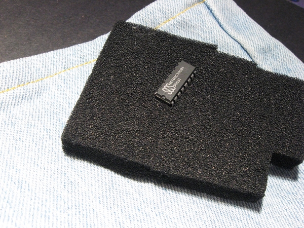
OTOH, if I place a 1/2" thick piece of black antistatic ESD foam, the acoustic energy goes thru. So a target beyond the foam is what gets detected. Some of the energy is getting absorbed or dispersed since the ability to detect objects beyond the foam is reduced.
Not sure if this is what you're after but it is interesting how the antistatic foam is like glass to an infrared beam.
Attachments
@stan2004 posted:OK. I'm game for a snipe hunt!
So if I place 1 or 2 layers of denim (from a pair of jeans) in front of sensor, it simply reflects back and the sensor detects it. I have way to see how much energy went thru the denim since the ECHO pulse width drops to the distance to the denim.
OTOH, if I place a 1/2" thick piece of black antistatic ESD foam, the acoustic energy goes thru. So a target beyond the foam is what gets detected. Some of the energy is getting absorbed or dispersed since the ability to detect objects beyond the foam is reduced.
Not sure if this is what you're after but it is interesting how the antistatic foam is like glass to an infrared beam.
Infrared beam? You've been working with that other technology too long! ![]()
Stan, you get an A+ on today's lab experiment, plus extra credit. ![]() I'm a little surprised that the denim is so acoustically reflective at 40kHz. Conventional wisdom in the applied acoustics field indicates that denim should be very absorptive throughout the higher audible frequency range (2.5k-20kHz). But based on practical applications and personal observations, I have often wondered if that may be incorrect when it comes to frequencies above 10kHz or so.
I'm a little surprised that the denim is so acoustically reflective at 40kHz. Conventional wisdom in the applied acoustics field indicates that denim should be very absorptive throughout the higher audible frequency range (2.5k-20kHz). But based on practical applications and personal observations, I have often wondered if that may be incorrect when it comes to frequencies above 10kHz or so.
As an example, most Noise Reduction Coefficient charts claim an essentially flat NRC around 1 above 4kHz for most absorptive materials (1 being 100% absorptive and 0 being completely reflective).
Based on your findings it seems clear that denim is in fact too dense to absorb much of the 40kHz energy produced by these transducers. It is possible that a softer looser weave cotton material like fuzzy flannel or uncompressed yet sufficiently thick multi-layered gauze could be more absorbent at 40kHz.
It may also be that the wave energy intensity, especially close to the transducer (see inverse square law for sound) would be too intense for effective absorption without going to extreme measures.
It's also possible that discovering an ideal inexpensive material that would be easy for most people to implement is probably well described (in your words) as a snipe hunt. Thanks again for contributing to the greater knowledge base here on the forum.
GRJ, could you post the final BOM? I want to make sure I have correctly fitting parts in hand.
Stan, I will as soon as I add all the parts to the design so I can print it. ![]() I used generic parts to size things like 1/4W resistors.
I used generic parts to size things like 1/4W resistors.
Here's the BOM for the project.
HC-SR04 Ultrasonic Train Detector BOM.pdf
Attachments
Thanks for the BOM; I needed to confirm the footprints on various parts so I could order what I didn't have. I supposedly just made the cut-off for parts from China as their New Year shutdown week is starting. We'll see...
@sjbuff posted:HC-SR04 Ultrasonic Sensor
Train Detection Block Signals
I thought I share the use of this ultrasonic sensor, I was able to utilize the sensor in my outdoor dead rail layout as a train/block detection on my layout.
Since converting the Baldy & Palms Railroad to “dead rail” in early 2021, the track detection circuit on the upper loop has been functioning correctly about 80% of the time. The reed switch circuit would get triggered by the magnets at one end of the block and not at the other end. This made the circuit go out of sync. I decided to try several other sensors with the Arduino to find a suitable solution. I tried the current sensor, voltage sensor, relay circuit, and the IR sensor, none of these performed reliably.
I discovered the HC-SR04 ultrasonic sensor and decided to experiment with this sensor. I also created a better Arduino code with the HC-SR04 sensor. I adapted the HC-SR04 sensor to fit in a small signal shed to match and blend with the block signal. The Arduino code is written so the HC-SR04 monitors motion from about 4 to 8 CM across the track. When a train is detected on one end of the block, the signal will turn red, and remain red until the train exits the other end of the block, at which the signal will reset to a clear green signal. This can be used with two or three aspect signals. The code just needs a few lines of code activated. The circuit has performed very well, so I plan to incorporate this circuit in other trains detection blocks on the layout. Check out the YT video for the Arduino code sketch and circuit design. YT Video - HC-SR04 Block Signal
Hope this post helps other outdoor layouts having the same problem and eliminate the need to put magnets on locomotives and rolling stock.
I must ask this question, in G scale we use a simple magnet reed switch and timed relay for our trains. Works great and the switch just drops between the rails.
@stan2004 posted:Thanks for the BOM; I needed to confirm the footprints on various parts so I could order what I didn't have. I supposedly just made the cut-off for parts from China as their New Year shutdown week is starting. We'll see...
I needed to generate that anyway, so it was no big deal. Hopefully, the boards made it before the New Year cutoff, they're coming from China as well. ![]()
Looks like they're making them anyway...

Attachments
@ThatGuy posted:I must ask this question, in G scale we use a simple magnet reed switch and timed relay for our trains. Works great and the switch just drops between the rails.
Yes - I've been using the reed switch/magnet for awhile now, and received mixed results. Magnet would not trigger the reed switch often. In my case once the magnet triggered the signal, the other end of the block would trigger the signal back to clear. If the reed switch missed the trigger, the block would not clear. I found the ultrasonic sensor more reliable in my situation.
Not as fast as they claimed they would ship, but inching their way through the PCB production process. ![]() According to the first estimate, they should have shipped a few days ago and with DHL, I would have had them by now.
According to the first estimate, they should have shipped a few days ago and with DHL, I would have had them by now. ![]()

Attachments
This is a really neat project! After finally getting caught up with the thread, I'll be following along and trying to keep up. Thanks to the OP for posting and thanks to everyone else involved for sharing your knowledge!
Getting closer, the boards are completed, they should be shipping them soon. I should have them within a week if DHL is awake.

Attachments
@gunrunnerjohn posted:Getting closer, the boards are completed, they should be shipping them soon. I should have them within a week if DHL is awake.
I think my parts might just beat you to the finish line. I see that JLCPCB and LCSC.com (where I ordered parts) are affiliated and perhaps the same company. In any case I ordered the parts when you ordered the boards. My tracking suggests the package did come by air and is somewhere in the US presumably to be given to USPS.
Meanwhile, I was hunting around and am astonished by the wide distribution of the HC-SR04 module.
Amazon has multiple sellers. eBay has multiple sellers - and even multiple sellers at 78 cents with free shipping from Asia (takes about 2-3 weeks). Even DigiKey is/was in the game though I think it was more a "convenience" item given their pricing. I think there must be some factory in Asia cranking these things out as fast as they can!
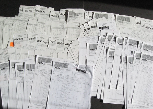
Anyway, since we're cooling our heels waiting for stuff, on separate note, I am comfortable recommending LCSC.com for componentsif you aren't in a rush. In this project, I knew the boards wouldn't be here for a few weeks, so I was able to find a single-source for components I did not have in GRJ's BOM. First off, to be clear, I am a fan of DigiKey and have been purchasing components from them for over 40 years! Here's a fun photo of a sample of my DigiKey packing slips!
I'm only talking about hobbyist orders and prototyping quantities...I don't have anything useful to say on comparing LCSC vs. DigiKey for production ordering (quantities in the thousands or millions).
I compared pricing for some parts in the BOM. I was too lazy to figure out how to make a neat table but here's the qty 10 pricing for LCSC vs. DigiKey:
0.022 capacitor 12 vs. 17 cents
220uF capacitor 7 vs. 22 cents
200K trimpot 9 vs. 40 cents
555 timer IC 16 vs. 32 cents
7805 voltage IC 23 vs. 52 cents
2-pin screw terminal 13 vs. 53 cents
G5LE 10A relay $0.60 vs. $1.57
eBay (Asia seller) will typically offer better pricing on any given component. But when you need a variety of parts in small hobbyist/prototyping quantities, it is a nuisance and roll-of-the-dice to buy one part here, one part there, from multiple eBay sellers. Like DigiKey you will be overwhelmed by the LCSC.com website when you get inundated with hundreds or thousands of choices for a simple component description...and then struggle to narrow down the choices via sometimes cryptic selector columns.
Bottom line. I've noticed a lot more interest/ability for guys on OGR designing their own PC boards. I suppose a lot of this is from the low-cost fabrication options like OshPark and free PC board design software. That said, and given that it typically takes 2 week or so to receive boards (unless paying usurious expedite fees), perhaps it's worth a look at LCSC.com for components.
Attachments
Looks like the boards have shipped as well. Apparently, DHL just thinks shipment info received, so I'll probably have it in about 3-4 days.
Thank you for your order from JLCPCB. It’s our pleasure serving you. We are pleased to inform you that the items listed below have been shipped via DHL International Express. Tracking Number: 9975697034,

Attachments
@stan2004 Thanks for sharing the tip about LCSC.com. Their pricing is very impressive.


