
sold delete
Original Post
|
|
sold delete
Replies sorted oldest to newest
Dave,
pick up some nylon plastic wire mounts. They have an open 'P' shape with a mounting hole in the leg(s) to screw it in. they are about ½" wide. simple and cheap, they also come in various sizes.
though I do not know the technical term for it.
Try spliting some pvc in short sections for brackets.
Wire management
Ship augered 1" holes work well.

Plastic non-metalic sheath staples work well
Cable ties also add to the organization.

Plastic wire tray may also help.


HomeDepot website. Garner Bender 1/2" plastic staples.

Cable ties. 8"

They also make a Wire Tye with a tab for a mounting screw.
I would suggest the plastic conduit hangers, just screw in one side and you can insert and remove wires with ease.

Typical module run

Triple 1 1/4" wire management holes seem to provide for an average linear layout.

This module has four courses, two high two low.

I'm kinda a one trick pony but it works. Consider boring a hole in the center third of the cross member not any larger then 1/3 of the total height, finish off with a 5/16 round over router bit.
However if you have assembled benchwork with decks already in place, CWEX's idea is the simplist approach. Just get a bunch of the 2" gray conduit clamps from the electrical department. Mount them on benchwork frames with a single screw as Chris mentions.
Mike's wire channels are very practical to service and reconfigure. I do use clamps like PRR Chris mentions but can be a pain to add/change wires.
No that's not me, that Tom has way too much hair.
![]() One of the things I do is to use different color wire for each leg of each circuit. When running a DCS star patterns I use different color tape on same circuit color wire pairs to differenciate that particular pair as they bundle just before the PDB-! boards. This is a small layout so all wires are 12 ga.
One of the things I do is to use different color wire for each leg of each circuit. When running a DCS star patterns I use different color tape on same circuit color wire pairs to differenciate that particular pair as they bundle just before the PDB-! boards. This is a small layout so all wires are 12 ga.
Just one of many ways to wire your layout. tt


Dave:
It's good to know you have a wiring plan about seperating wiring. Add to that plan and allow for a systematic install. There is a wealth of application technique in a few post here. Keep in mind that I have changed and added to my original install. The wire tray was too small and some had to be changed. The Atlas 6924 relay upgrade also changed a lot. The world changes a bit each day. My TMCC state of the art equipment from 10 years ago is obsolete, so I guess I have some more changing to do or let it all collect dust. It is great to have an operational layout.
Your Lionel Grain Elevator still looks great.
Mike
Mike I remember when you first posted those tray photos. Whose product? Wider/deeper trays available?
Also, years ago I was using a wire labeler which stamped A/N part numbers on the wire every so many inches as you pulled the wire through it. Lost the marker in a move and no idea of mfg. source, ring a bell with you?
FWIW,
here is what I use for Cable Management on my Modular RR being constructed now...


Cable Tie Mounting Pads....


Grainger Wire duct product.
There are covers and a different assortment of widths and depths.
The covers installed.
all my wiring comes to the front of the layout and is hidden by mounted fascia.
Mike, I haven't got that far yet but your elect. board looks scary as none of those boxes look familiar. Silver ones and tans ones and black and many others. Golly, And then who knows what else you got going on under your table.
1. Also consider color coding your wires.
2. RS did have nails and holders for routing RG-58 and 8 "ham" coax cables. for a few wires in a local location, they do work well. I sub a screw for the nail!
3. Hams have started to use Anderson Power Poles for connectors. Red and black for 12 V dc. But they do come in diffented colors and sizes for you power and wiring needs. Disadvantage: They are hand to place the wire in the connector which goes into the plastic base.
There is a "TMCC/L/DCS" group on this blog. There might be people there to help.
Actually, I got a like crimper from MFJ. Need to try with APP's. Also It works weel with crimping wires, like the C-ends for bus connectors.
Got some APP "rat tails" so my radios can work with APP's. I am surprised the radio importers have not gone to APP's as standard.
TomTee - I saw your pictures and video on YouTube with the liftable bridges for accessing the inner parts of the layout. How do you power these segments? I saw the drop-in brass plugs you use to get the tight alignment, i'm guessing perhaps that has something to do with it. Love the idea of a removable segment to get into the middle of the layout. I've never done portable benchwork, so I'm not really sure how things fit together and are powered when they dont have the little edge connectors between the track pieces. Tips appreciated! Thanks
Grainger Wire duct product.
There are covers and a different assortment of widths and depths.
The covers installed.
Hi Mike CT
IMHO this is a neat job of wiring. Is that a DCC system I see? I dont recognize the manufacturer. Can you elucidate?
John
This is my layout ![]()
I see nothing wrong with that...![]()
This is my layout ![]()
You forgot to color code your wires. Lol. It doesn't look like your too far along there so easy to start over.
Grainger Wire duct product.
There are covers and a different assortment of widths and depths.
The covers installed.
Hi Mike CT
IMHO this is a neat job of wiring. Is that a DCC system I see? I dont recognize the manufacturer. Can you elucidate?
John
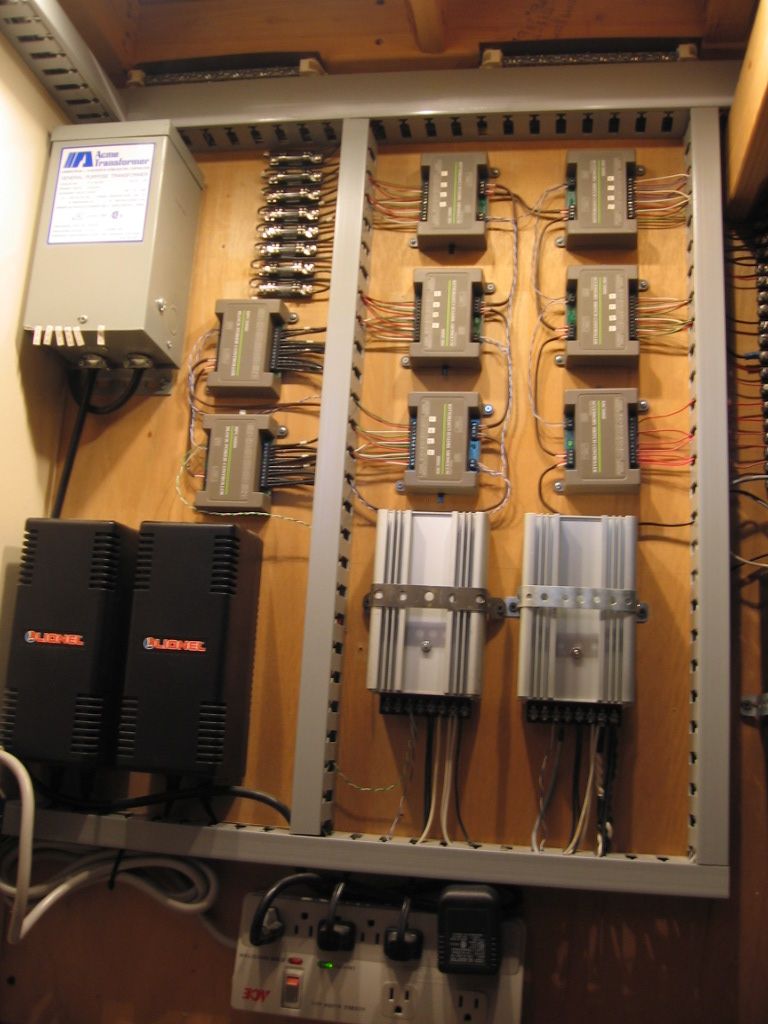
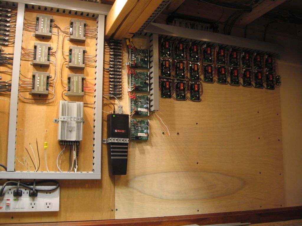
This is an older Lionel TMCC control system. The control devices are (2) TPC 400's, (Track Power Controllers), the large silver boxes. Note the two Lionel PH 135 Transformers lower left. Grey/tan boxes, middle left, are IC Controls BPC, (Block Power Controllers). These BPC turn power on and off to (8) different track blocks. They can also switch power from one TPC to the other. IC controls was eventual purchased by Lionel. The middle grey/tan boxes are ASC's, Accessory/Switch Controllers. Most control switches, one is for accessory control. The TPC's, BPC's, and ASC's are all controlled via the Lionel Command Base (Black box lower middle) and Cab 1 handheld remote. To the far right are a lot of Atlas 6924 Switch control boards. Each control board operates an Atlas track switch or combination of switches for crossovers. Somewhere in the middle there are (4) control boards that operate crossing gates. Upper left are (8) fuse blocks for track power. A larger fuse system, middle area, protects switch/accessory power. The rest is wall wart transformers and power supplies. The control system has evolve over the years. It is still changing. Thanks for asking, Mike
My junky panel can't hold a candle to Mike's, but I also used Panduit wire duct.
![]() Looks really good to me
Looks really good to me![]() You have added DCS. I have yet to make that step. My Grandson Micah was here last weekend with his new engine. We hooked-up a TIU temporary for his engine. It seemed to work O.K. Always a next step. IMO the key is some system of organization.
You have added DCS. I have yet to make that step. My Grandson Micah was here last weekend with his new engine. We hooked-up a TIU temporary for his engine. It seemed to work O.K. Always a next step. IMO the key is some system of organization. ![]() Mike
Mike![]()

Mike, thank you for your kind words. There are however two pretty serious flaws in my panel.
Despite my original plans, there is not 25% unpopulated free space for future expansion. This panel is 60" wide (as you are viewing it). It should have been made 72". There was room for the larger panel to begin with. Your panel has more than adequate room for expansion.
I used 2x2 Panduit. Should have used at least 2x3. Once wired, I fully expect to exceed the 40% fill limit on the ducts.
I already have a 30x30 "Daughter" panel to accommodate expansion. Scabbing over to another panel is going to look bush-league. I will likely slide the second panel over to the other side of the layout to make it look like I meant to do it that way.
In the panel business, this first one would have been scrapped and we'd be starting over with the proper sized back plane. If my buddy Will were to see this, the chin music would be non-stop from now until next Christmas.
Gilly
Mike, thank you for your kind words. There are however two pretty serious flaws in my panel.
Despite my original plans, there is not 25% unpopulated free space for future expansion. This panel is 60" wide (as you are viewing it). It should have been made 72". There was room for the larger panel to begin with. Your panel has more than adequate room for expansion. Panel space has been adjust, to the right, installation of the 6924 relay boards was an addition.
I used 2x2 Panduit. Should have used at least 2x3. Once wired, I fully expect to exceed the 40% fill limit on the ducts. I have replaced a couple of pieces of 1X2 wire duct with 2X2. It is amazing how much wiring there is to a layout. ![]()
I already have a 30x30 "Daughter" panel to accommodate expansion. Scabbing over to another panel is going to look bush-league. I will likely slide the second panel over to the other side of the layout to make it look like I meant to do it that way.
In the panel business, this first one would have been scrapped and we'd be starting over with the proper sized back plane. If my buddy Will were to see this, the chin music would be non-stop from now until next Christmas. Pictures of average installs on the forum are not un-common, and I can appreciate some of the struggles that a hobbyist would have with this. Hopefully some of this information will be of help.
![]() Mike CT
Mike CT![]()
Gilly
Access to this requires an OGR Forum Supporting Membership

