In this multi-part post I'll take you along the adventure of building a Locomotive Workshop's E9 kit.  Interest in building a locomotive kit occurred after I signed up to be a digital subscriber to O Gauge Magazine.  Alan Arnold has given us access to an incredible research tool and I would recommend all forum members sign-up to be an OGR digital subscriber.  I began reading these early OSR magazines cover-to-cover to learn more about our hobby.  Starting at issue #1, I learned of the different obstacles facing model railroad hobbyists at the time.   It seems during the late 60’s and early 70’s O scale trains were going through rough time.  The HO train market was getting huge and taking over the hobby.   There wasn’t a lot of O scale manufactures at the time and only a few of them made scale locomotives.  50 years ago if somebody in our hobby wanted a true "scale sized" diesel locomotive in a specific style or paint scheme, they had to build it.

By the time I hit OSR magazine issue #14, I read an advertisement that stated Locomotive Workshop was going to have an E9 diesel kit available in the near future for $59.50.  The ad's description read:  The E9 kit was sold basically complete except for the mechanism.  Includes basic body and soft metal trucks.  Brass engraved - photo engraved brass - brass photo etched body.  The nose section on this E9 kit was a lost wax brass casting.   

For me, building an unassembled locomotive from a kit was a completely different aspect of the model railroading hobby.  Ok then... I was willing to give it a try.  Looking online I found an unbuilt Locomotive Workshop E9 kit for sale and clicked Buy-Now.  The kit arrived at my house a few days later.  Here's what the parts look like laid out across a table.

thumbnail_IMG_9156


The literature that came with this kit said it could be built as O – ON3 – Hi Rail.  I decided to try and build this E9 diesel locomotive for Hi-Rail so it can run on my layout.  An article in the OSR magazine mentioned they made small production runs of only 25 to 30 units at a time and shipped orders from this inventory.   The business location on the original shipping label and all paperwork included in the box showed Avon Lake, Ohio.  That’s interesting because Locomotive Workshop's mailing address changed in the January 1973 issue #31 of OSR issue to Englishtown New Jersey.  At this point all clues showed this E9 kit was pre-January 1973 inventory and probably from the first production run in 1971.

thumbnail_IMG_9162


The best I could figure, the original owner paid $59.50 for this kit.  That would calculate to around $399.00 in today’s dollars.  That seems like A LOT of money today for an unbuilt kit.  But times were different back in 1971 and building a kit was the only way they had to get the exact diesel locomotive they wanted.


Click the like button below to follow this thread and stay tuned for the next update in this adventure.

Attachments

Images (2)
  • Unbuilt Locomotive Workshops E9 kit
  • Choose Hi Rail
Last edited by T.Albers
Original Post

Replies sorted oldest to newest

Personally I have never built a brass kit although the E9s are an interest of mine (specifically the UP engines and I have the latest Legacy version of the 949-951 A-A set).

I have always reckoned that I do not have the soldering skills for construction although I have done a minimal amount of resistance soldering. Plus there is the painting prep and actual painting, although from your previous posts you have all the skills, and more, needed for that!

Very much looking forward to seeing how you get on.

My only project of a similar kind is converting a Legacy SuperBass E7 B unit to run with the E9 set:

E9s_A-A

For whatever reason, Lionel has never produced any E8/9 B unit, or at least not one of scale dimensions. MTH has done a scale E8 in their Premier line, which is close enough for my purposes at least in terms of appearances. I have tracked one down and it will be a matter of my usual crude kitbashing to see if the shell will fit on the Lionel E7 chassis. The colors are generally a close match.

Attachments

Images (1)
  • E9s_A-A

I've built a few LWS locomotives, including this UP DDa40x.  While the kit parts photo shows all the exterior parts, there is no interior floor or underframe.  You will need to make an underframe with supports for the motor(s) and truck mountings. Also the coupler mountings on each end, and get the locomotive to ride at its correct scale height.  On the DD, using brass structural parts, like "I" beams, "C"s and "L"s, I made an underframe to hold two Pittman 9xxxx motors, each driving a truck through Central  Locomotive Works transmissions. A floor was put in only under the cab, which was detailed inside.

The sprung, soft metal trucks were reinforced with brass backing plates and fitted with brass journals for better wear resistance. Because the DD is such a long locomotive, I made articulated coupler mountings for each end to enable the couplers to swing wide and remain close to center on curves. It was able to negotiate a 60" radius curve, but had a good deal of mid-body side overhang in doing so.  A 72" radius was better. It could haul a 60 car freight with metal wheels a scale 65 MPH. The roar from all those wheels was almost deafening!  I built it for a friend and fellow O scaler who has since passed away. His family sold the model and I have no idea where it went.

In this photo, taken when finished in 1980, it is standing on a  section of road bed with steel, hand-laid NY Society of Model Engineers AAR profile rails that were custom rolled in the late 1930's. It was once a part of General Electric's model railroad club O scale layout in Schenectady.  The ballast was made with roofing shingles glued on to pre-cut plywood roadbed.

                     UP6905a

S. Islander

Attachments

Images (1)
  • UP6905a: LWS kit built UP DDa40x completed in 1980.

Very interesting for sure'.  I look forward to seeing the final finished model. What are you going to use for motor power and lighting?

Thanks @Quarter Gauger 48 .  I remember a comment you made I while ago about how much it costs to add little brass details on these trains.  My wife already calls this one the "gold" engine.  I'm hope she is referring to the locomotives metal's color and not how much its going to cost to get it running.   lol

For power/control, I was planning on reusing an older TMCC control board that got pulled out of a working engine during an EER upgrade.  It only has terminals for the front LED headlight.  The cost was right and I will only be sacrificing a backup light and independent cab lighting.

Last edited by T.Albers
@Hancock52 posted:

Personally I have never built a brass kit although the E9s are an interest of mine (specifically the UP engines and I have the latest Legacy version of the 949-951 A-A set).

I have always reckoned that I do not have the soldering skills for construction although I have done a minimal amount of resistance soldering. Plus there is the painting prep and actual painting, although from your previous posts you have all the skills, and more, needed for that!

Very much looking forward to seeing how you get on.

My only project of a similar kind is converting a Legacy SuperBass E7 B unit to run with the E9 set:

E9s_A-A

For whatever reason, Lionel has never produced any E8/9 B unit, or at least not one of scale dimensions. MTH has done a scale E8 in their Premier line, which is close enough for my purposes at least in terms of appearances. I have tracked one down and it will be a matter of my usual crude kitbashing to see if the shell will fit on the Lionel E7 chassis. The colors are generally a close match.

Thanks @Hancock52 I have never build a brass kit before either.  My experience so far has been the ability to solder two electrical wires together.

The new Lionel legacy engines are beautiful and I will be trying to specifically duplicate the Union Pacific E9's.   A few day ago I ordered Volume 8, Issue #4 from the Union Pacific Historical Society that has information about the E9's.  This issues has an article by Robert Darwin that is suppose to cover UP’s new passenger diesels that were delivered in mid 1950's.  I'm hoping it also has lots of detailed photos.   I will let you know if it turns out to be a good issue.

Since my wife has taken a liking to this golden engine I don't plan on painting it.  It's still a long ways away, but I read on the forum that brass can be painted with a clear gloss to keep it from tarnishing.

Keep me updated on your B unit project.  I would like to do make a brass B unit at some point also.

Last edited by T.Albers
@Norton posted:

I was going to ask the same question. Might be easier to find a complete frame with drive. There are a number on eBay now. If you can’t find one thats appropriate PM me for a source.

Pete

Hi Pete, yes that's my plan.  I have a lead on a used E8 frame/chassis with twin DC can motors and committed to purchase it from the seller.

If this build turns out successful I would like to find a matching B unit frame and will definitely reach out to you.

Last edited by T.Albers
@GG1 4877 posted:

I am looking forward to seeing your progress.  I want to learn more about working with brass myself for a future projects.

Thanks @GG1 4877, I have been working on this kit all day and it's going slow.  Not impossible, but really slow.

After a days work I don't have any new progress to show you guys.  This my first time trying to build an O scale kit.  And my first brass anything.  I think I dove straight into the deep-end by choosing a brass locomotive.  🙂

I don't know if I'm going to make all the right decisions while building it but I'm going to learn!

@S. Islander posted:

I've built a few LWS locomotives, including this UP DDa40x.  While the kit parts photo shows all the exterior parts, there is no interior floor or underframe.  You will need to make an underframe with supports for the motor(s) and truck mountings. Also the coupler mountings on each end, and get the locomotive to ride at its correct scale height.  On the DD, using brass structural parts, like "I" beams, "C"s and "L"s, I made an underframe to hold two Pittman 9xxxx motors, each driving a truck through Central  Locomotive Works transmissions. A floor was put in only under the cab, which was detailed inside.

The sprung, soft metal trucks were reinforced with brass backing plates and fitted with brass journals for better wear resistance. Because the DD is such a long locomotive, I made articulated coupler mountings for each end to enable the couplers to swing wide and remain close to center on curves. It was able to negotiate a 60" radius curve, but had a good deal of mid-body side overhang in doing so.  A 72" radius was better. It could haul a 60 car freight with metal wheels a scale 65 MPH. The roar from all those wheels was almost deafening!  I built it for a friend and fellow O scaler who has since passed away. His family sold the model and I have no idea where it went.

In this photo, taken when finished in 1980, it is standing on a  section of road bed with steel, hand-laid NY Society of Model Engineers AAR profile rails that were custom rolled in the late 1930's. It was once a part of General Electric's model railroad club O scale layout in Schenectady.  The ballast was made with roofing shingles glued on to pre-cut plywood roadbed.

                     UP6905a

S. Islander

@S. Islander that DDa40X is fantastic!  I read in OSR issue #37 Locomotive Workshops was going to produce this engine in brass and the #6905 you built looks amazing.  Do unbuilt brass DDa40X kits still come up for sale online or at train swap meets?  I don't know how many of these DDa40X kits Locomotive Workshop could have manufactured for customers being it takes a massive layout to run, especially if your pulling 60+ freight cars.  👍 

Thank you for the helpful building tips.  I have been finding the Locomotive Workshop instructions less then complete.   

Update Feb 14th

I wasn't planning on doing a step-by-step how to article on the proper way to build a brass locomotive because I have never build one before.  The hope is to share my first time experience of trying to build this brass kit so today’s forum members can learn.  In the March 1972 issues of OSR editor Corey Jones said “The object of this magazine is to provide the basis for sharing ideas and methods of model railroading in O Gauge… and O Scale”.

To build the kit correctly was planning on carefully following the detailed steps shown in the original Locomotive Workshop instructions.   1st Problem.  As @mwb mentioned above they don’t give step-by-step instructions!  This kit only included a suggestion sheet.   I needed more than just suggestions.  So, I put away the kit and went back to reading more issues of OSR to learn from model builders during this time period.


I found insight on building a brass locomotive in the February 1978 issue of OSR magazine (issue #54).  On page 14 of this magazine Dr. James F. Eudaly gave photos and covers general techniques on assembling a Locomotive Workshop's U-33c brass locomotive kit.  To assemble the different parts of the kit he used solder, epoxy and CA glue.   Armed with this new knowledge I open the Locomotive Workshop's instruction sheet again (scratch that, suggestion sheet) and started with number 1.

1. Cutouts:

There are a number of cutout to be made in the body shell.  The portholes and side door cuts may be made before soldering on the ends, but all roof cut should be held until the body in structurally complete.

That’s it… nothing more was said.  Well, honestly I didn’t like suggestion number 1.  The brass sides move under any kind of light pressure.  I decided it would be better to wait until after the body is more structurally complete and use 1” thick wood supports inside the shell to reinforce while drilling portholes.  Well, on to the next suggestion.

thumbnail_IMG_9197


2. Nose: Cutout the windshield before soldering the nose to the body of the shell.

There’s lots of difficult work to complete in that short little sentence of suggestion #2.  As you can see below only the fireman side of the brass nose casting has been cutout from the factory to resemble a windshield opening.   

thumbnail_IMG_9173


And the next part of section 2 it reads: On the E9, remove the number boards.

Ok then… it looks like only the fireman’s side of the nose casting comes from factory in a finished state.  Locomotive Workshop must be giving examples for the person building this kit and expects me to make the other side of the cab match.  At this point it's time to bring out the Dremel with cutting bit.  Also, I need to drive over to Harbor Freight today to buy their 12 pack of fine jeweler's files for the finishing work around the window.


Stay tuned for the next update in this adventure!

Attachments

Images (2)
  • Brass shell porthole
  • Brass nose casting
Last edited by T.Albers
@T.Albers posted:

2. Nose: Cutout the windshield before soldering the nose to the body of the shell.

There’s lots of difficult work to complete in that short little sentence of suggestion #2.

I remember in the "instructions" for my LWS PRR H1, "Assemble the mechanism".  Nothing more that that......so you really had to know how to build the kit w/o the instructions.  Except in my case the mechanism was a physical impossibility,

@Strummer posted:

Fascinating stuff; thanks for doing this!

Mark in Oregon

Thank you for the support @Strummer.  When I purchased this LWS kit I knew removing the extra brass from the window opening would be a turning point in this build.   I decided if I can successfully remove this extra brass materiel without messing up the window line then I will continue building.   If not, this adventure is over and it goes back into its box again.

thumbnail_IMG_9178


  I now have the files from Harbor Freight and will let you know how it turns out!

Attachments

Images (1)
  • Brass nose casting and E7 number board
@Johnbeere posted:

That window shouldn't be too hard to do. I suggest marking a line to give you some reference point as to where you need to stop filing. If you remove too much material, you could add more material by soldering something to it and filing that down.

Yes.  Decent files and patience are key components to success.

Good suggestions on the line / reference points!

This is how you learn to scratchbuild.  A couple of cautions and/or comments:  The nose appears to have been worked on prior to your acquisition.  Not at all sure it left LocoWorks that way - Jan did not generally provide brass castings, preferring something called "Brittania metal."  The window opening looks just a hair too large, although it is of the correct shape.  As above, a layer of brass on top and bottom, and file to shape is the key.

I have carved two such windshields in the last month - a PA and an E7.  I used a Dremel with carbide burr for the rough cuts, but it takes a steady hand and some experience.  Goes really fast.  Do not hesitate to spend money on good files, and remember - files get dull quickly and then become semi-useless.

If the sides are dead-soft (as in bend or deform easily) you are probably doomed.  Brass in the half-hard state works much more easily.  It is not impossible to make your own sides - you use maybe .025 or .032 HH brass, cut to shape, pinned and soldered to roof and ends, and then solder .010 battens, suitably impressed, on to the sides.  This is not easy, but it will teach you a lot about soldering, which is what your goal is.

DSC02944

Here is one I am working on - I did not do the rivet strips, but did straighten them out a bit, and added some vertical detail to the openings in the side.  You can see that the nose is similar to the one in your kit.

Attachments

Images (1)
  • DSC02944

Oh - one more.  On those portholes, you are better off drilling before assembly, but you absolutely need zero rake drill bits and a good drill press.  You need to clamp the sides securely on a wood block and to the drill press table.  "Step-drills" are usually zero rake, and work well on work that is properly clamped.

You need zero rake drills for all holes bigger than #56.  Difficult to buy, but you can dress regular drills with a Dremel cutoff disc and a magnifying glass.  Drilling brass with ordinary twist drills varies from unsuccessful to dangerous. 

@Hancock52 posted:

Wow, that is one rough casting of the cab section. I wish you luck trying to keep this in a brass finish - it obviously wasn’t intended to be left unprimed/painted. Be careful if you use an electric tool to grind excess brass away - from experience with polishing rough brass hardware, the dust is really no good for you!

Lol, yes... the cab section pretty rough.  It won't be winning any beauty contests!

It's a good entry level brass locomotive for a beginner like me.  And I will polish it up the best I can.

Last edited by T.Albers
@Johnbeere posted:

That window shouldn't be too hard to do. I suggest marking a line to give you some reference point as to where you need to stop filing. If you remove too much material, you could add more material by soldering something to it and filing that down.

Thank you for the helpful pointers @Johnbeere .  I didn't know I could add back material if I cut to much away.

This forum is great and has given me more helpful information about building a brass locomotive than all the original LWS instructions! 

@bob2 posted:

This is how you learn to scratchbuild.  A couple of cautions and/or comments:  The nose appears to have been worked on prior to your acquisition.  Not at all sure it left LocoWorks that way - Jan did not generally provide brass castings, preferring something called "Brittania metal."  The window opening looks just a hair too large, although it is of the correct shape.  As above, a layer of brass on top and bottom, and file to shape is the key.

I have carved two such windshields in the last month - a PA and an E7.  I used a Dremel with carbide burr for the rough cuts, but it takes a steady hand and some experience.  Goes really fast.  Do not hesitate to spend money on good files, and remember - files get dull quickly and then become semi-useless.

If the sides are dead-soft (as in bend or deform easily) you are probably doomed.  Brass in the half-hard state works much more easily.  It is not impossible to make your own sides - you use maybe .025 or .032 HH brass, cut to shape, pinned and soldered to roof and ends, and then solder .010 battens, suitably impressed, on to the sides.  This is not easy, but it will teach you a lot about soldering, which is what your goal is.

Here is one I am working on - I did not do the rivet strips, but did straighten them out a bit, and added some vertical detail to the openings in the side.  You can see that the nose is similar to the one in your kit.

Thank you for the detailed advice @bob2 .  I hope my project turns out as good as your E7 photo!   

I believe you are correct about somebody working on this brass nose casting before I got it.   The nose casting came with some deep scratches/gashes directly in front of the engineers window.  I don't think LWS would have sent out an expensive kit like this with those deep marks on the nose.     


thumbnail_IMG_9181

Attachments

Images (1)
  • brass nose scratches
Last edited by T.Albers

Update Feb 16th

Now I see why many of these brass kits don’t get built and end up being called doorstops.  This is not an easy model to build like a plastic airplane or battleship where there‘s a full diagram, everything’s labeled and the instructions are clearly written out.  And if you think about it this kit stayed inside its original shipping box for 50 years.  How many times did the original owner look at this unassembled kit and say… nope, not going to happen today.  Or, what was I thinking?

For years the early OSR magazines had advertisements from O scale kit manufactures with the slogan: Take pride in saying, I built it!  I sure hope I can say that at the end of this project.

The current problem I’m up against is the brass material that needs to be removed from the engineer’s window is more than “a little bit of flash” that gets trimmed-off with an X-Acto knife.   This extra brass material is as thick as the nose casting.

thumbnail_IMG_9179


I thought out my situation and decided to create a paper pattern of the good window from the engineer’s side of the cab.  I took this paper pattern and flipped it over.  Then, using reference point lines as suggested by @Johnbeere I traced the outline on the engineer’s side of the cab with a fine tipped ink pen.  With a Dremel and files I carefully removed the extra brass material from inside the engineer’s window all the way out to the marked reference lines.

Next, that single E7 style number board was progressively removed from the engineer’s side of the nose casting.  I started with a medium flat file, then switch to a fine flat file and I finally smoothed everything over with fine grain 800 wet/dry sand paper.

thumbnail_IMG_9220


Success!  Removing the extra brass worked just like you guys said it would.  That means this build will continue.  👍

Stay tuned for the next update…

Attachments

Images (2)
  • inside nose casting
  • extra brass removed from nose casting
Last edited by T.Albers
@Johnbeere posted:

Looks good! You may need to do some more work evening out the two windows, though, since they don't appear to be perfectly lined up. I know that would bug me a lot.

Now that you mention it . . . I also see that now but this is the old problem of not being able to duplicate machine-made accuracy.

The cab area has polished up nicely so far. If this is Britannia Metal I have worked with it before (not on scale models though) and found it more effort than brass. It's generally harder and stronger than brass or different tin alloys. It's generally silver/pewter in appearance so I don't know if this shell is plated or has been mixed in such a way as to produce the brass/gold coloring.

Well, you can get pretty accurate with a file if you take it slow. Just remove metal slowly until they line up just right, I'm sure he can do it. Were I doing it, I might get a straight edge, like a ruler, and use it to visualize how even the two sides are.

I assume it's just brass, brass is a very common metal for these old kits.

It looks like an Adams & Son nose.

When you get ready to solder the sides, remember that this is a two piece nose, and if you get it hot enough it will slip.  Run a bolt through the cab windows and snug it up. Wrap a damp rag around the nose.  Heat only the casting; never the thin sides, when attaching thin stuff to heavy brass.  And always clamp everything.

@Mike CT posted:

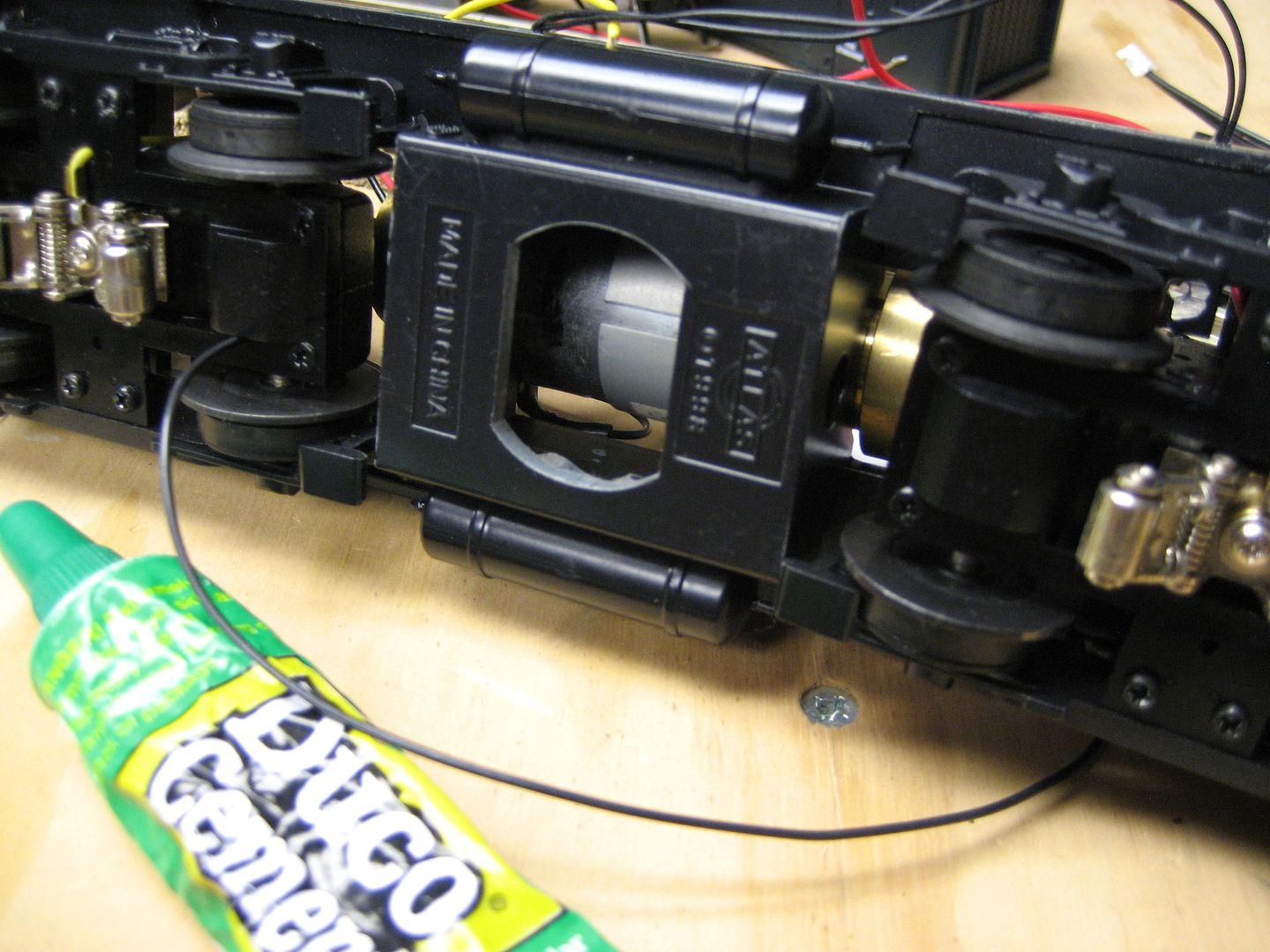
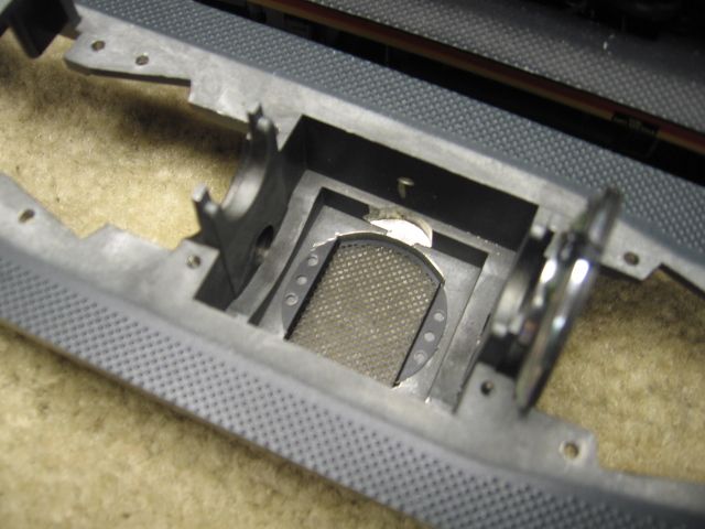
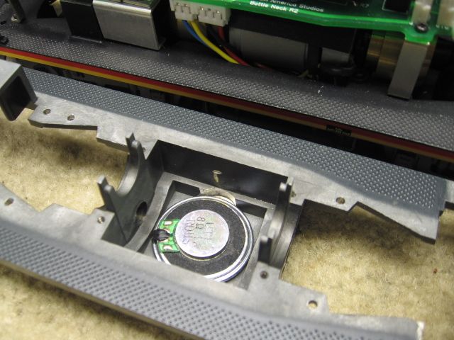
An early Atlas SW9 upgrade I used a dremel with a small milling bit to cut a hole for the speaker in the fuel tank.  Finish cut was done with small hand files.

Otherwise your other option is get the Lionel E8 fuel tank which has the speaker cut out and speaker mount in it. dont forget to order the air tanks and the screws as well! Lionel parts is all A la Carte!

Add Reply

Post

OGR Publishing, Inc., 1310 Eastside Centre Ct, Ste 6, Mountain Home, AR 72653
800-980-OGRR (6477)
www.ogaugerr.com

×
×
×
×
Link copied to your clipboard.
×
×