As one of the electrically challenged , here's my scenario and question:


I am trying to determine how many lights I can successfully put on an accessory transformer's circuit.  I have a 12v tap and the following lights (Column1 = voltage; column2= # of lights):


MTH   Bank Building, SW Steubenville144
Steubenville Train Station142
Richmond Brothers142
Archie's Place (bar)141
Burke Building (front)143
Toy Shoppe (2 story)142
Lionel Coal Tipple 141


I know I could just keep adding bulbs until they all go dim, but I would prefer knowing how to calculate the load to determine if it will work. 


Many thanks and my apologies for such a stupid question.


George


Original Post

Replies sorted oldest to newest

George


Great question.  We need to know what transformer you are using and its wattage.   Are these incandescent bulbs?


The general rule is that each incandescent bulb consumes about 3 to 4 watts.  So the total wattage is 45 to 60.   If your accessory transformer is rated at 100 watts or more you are ok.  With older PW transformers, the wattage rating is peak and not sustainable.  Therefore an old PW transformer rated at 100 watts is really capable of close to 70 watts.  good luck

Tony,


Thanks - to answer your questions...


The power source is a K-Line PowerChief 120F accessory transformer.  It has a number of taps - 3v, 5v, 8v, 12v, 15v, and 20v.  I had planned on using the 12v or 15v tap (and others if power is available).  I do not know what this tranformer is rated at total (and don't have it in front of me).


And these are all incandescent bulbs.  I have some 18v LEDs that I could add afterwards as they are basically too small a draw to be a factor (or so I understand).


George

Not a stupid question.  Your transformer is rated 120 watts.  Limit Transformer loads to 75% of the continuous load.  You have 90 watts available for a continuous load.


Assuming incandescent lamps and 3 watt bulbs multiply 3 x total lamps of 15 = 45 watts.

75% of 60 watts = 45 watts.  Your minimum transformer rating would be 60 watts.


For circuit protection use 45 watts divided by 14 volts = 3.5 to 4 amps.


These are rough numbers but are useful as a guide.


George

If the number of lites grows to a much larger number, you can consider using relays to supply the power to them. The relays work well if you also intend to keep some of the layout dark [off] some of the time and you plan to use toggles to turn them on/off.


Dale H. posted some of this on the JCstudio site. you may want to look there or i'll see if I can find/scan the wiring schematic and email to you if you are interested.

Ralph

Originally Posted by Susan Deats:

Not a stupid question.  Your transformer is rated 120 watts.  Limit Transformer loads to 75% of the continuous load.  You have 90 watts available for a continuous load.


Assuming incandescent lamps and 3 watt bulbs multiply 3 x total lamps of 15 = 45 watts.

75% of 60 watts = 45 watts.  Your minimum transformer rating would be 60 watts.


For circuit protection use 45 watts divided by 14 volts = 3.5 to 4 amps.


These are rough numbers but are useful as a guide.


Susan, I have a follow-up question / confirmation.  So, if I decided to use the 45 watts for the lights described above, I still have roughly half (another 45 watts) available to me regardless of which voltage tap I use, correct?


And by circuit protection, you're advising me to place a 3.5 amp fast acting fuse in the circuit between the transformer tap and the first lighted structure, right?


Oh, and one more question.  Does it matter at all if I use a buss (series) or terminal strip (parallel) to supply juice to these lights?


Thanks,


George

Last edited by G3750

All:


Many thanks for the responses and very useful information.  I believe I have solved my problems (discussion is also part of the topic Indoor / Outdoor Lighting Transformer).


Here's what I'm going to do:

  1. K-Line PowerChief 120F #1, which is currently using its 15v tap to power all 21 DZ-2500A switch machines, 4 DZ-1060 PRR signals, and 2 MTH PRR signal bridges, will remain "as-is".  I may add two DZ-1010 crossing gates to it.  All these (except the signals) are transient loads activated by rails or pushbuttons.
  2. K-Line PowerChief 120F #2 will be used to power AC accessories all over the layout.  Power distribution will be via buss.
  3. 300W Power Supply #1 will be dedicated to the western side of the layout.  This device will provide 3VDC, 5VDC, and 12 VDC as needed.  My understanding is that light bulbs do not care whether power is AC or DC.  Distribution will be thru terminal strips for each voltage.
  4. 300W Power Supply #2 will be dedicated to the eastern side of the layout.  This device will provide 3VDC, 5VDC, and 12 VDC as needed.  My understanding is that light bulbs do not care whether power is AC or DC.  Distribution will be thru terminal strips for each voltage.

I'm thinking that both 300W powersupplies will end up on the tranformer cart, controlled by 1 ON/OFF switch.  Also, I don't think I need fast acting fuses between the devices and the transformer.


Thanks again!


George

Originally Posted by gunrunnerjohn:

Just one comment.  I think you need some sort of reasonable circuit protection between the transformers and the load.  300W is more than enough to start a fire if you don't have circuit protection!

John, in that case would a fast-acting fuse for each of the voltage feeds just before the terminal strip be sufficient?  What size of fuse would you recommend?


Thanks,


George

Originally Posted by G3750:

Susan, I have a follow-up question / confirmation.  So, if I decided to use the 45 watts for the lights described above, I still have roughly half (another 45 watts) available to me regardless of which voltage tap I use, correct?


And by circuit protection, you're advising me to place a 3.5 amp fast acting fuse in the circuit between the transformer tap and the first lighted structure, right?


Oh, and one more question.  Does it matter at all if I use a buss (series) or terminal strip (parallel) to supply juice to these lights?


Thanks,


George

Yes, you have a minimum of 45 watts left over.

Yes, the 3.5 amp fuse will protect that lighting group/circuit.


Your lights must have parallel wiring.  In general our toy train layouts do not use series wiring.  See the diagram at top of this page, Layout Wiring and substitute "all your lights" in place of "3 Rail Track" reference on the diagram.


One wire from each of your lights will be tied directly to the common on your transformer.  The other wire from each of your lights will be tied to the output of the fuse.  You would have two terminal strips (1 from common and 1 fused) that are common (all taps tied together).

Originally Posted by G3750:
Originally Posted by gunrunnerjohn:

Just one comment.  I think you need some sort of reasonable circuit protection between the transformers and the load.  300W is more than enough to start a fire if you don't have circuit protection!

John, in that case would a fast-acting fuse for each of the voltage feeds just before the terminal strip be sufficient?  What size of fuse would you recommend?


Thanks,


George

A fuse or circuit breaker is certainly called for.  I generally like to size the fuse for low power circuits at 2x the actual draw.  For higher power, say 10A from a transformer, I'd probably consider a 15A fuse.

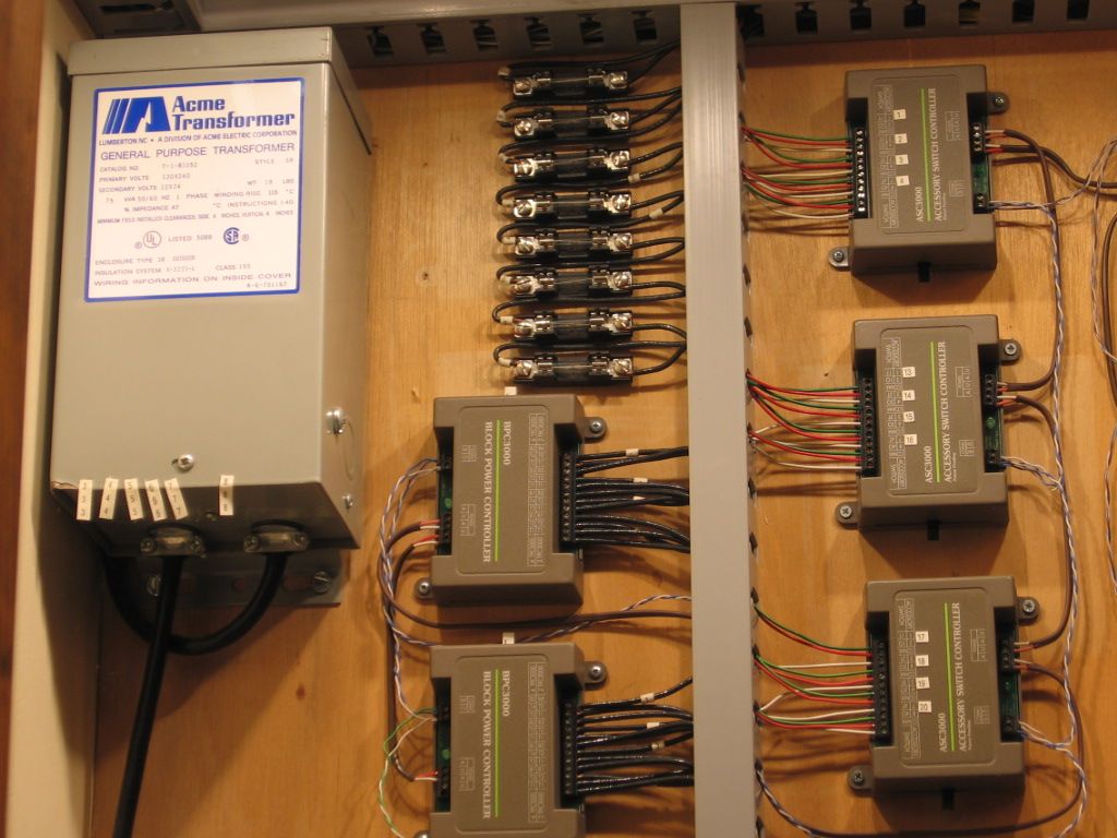
Circuit protection. Fuses can be purchase at any auto parts supply.  The pictured fuse block will handle fuses and wiring up to 30 amps.  Model train circuit design usually requires much less.  There is quite an assortment of fuse sizes available.  I use 7.5 amp for track power supply and a lot of 3 amp fuses for accessory power.  In some case you may want to use smaller fuses.  Click on the underlined phrase to link a Grainger Supply detail page.  My experience, anything over 10 amps, a derail was arc/spark and welding. Grainger fuse selection chart (AGC fuses).

Last edited by Mike CT

This consist runs well at 7.5 amps.  Usually figure about 1.5 to 2 amps run per unit. These single motored Atlas SW seem to draw a little more than the average (2) can motor unit.  If you have issues on run at the lower amperage, (7.5 amps), the circuit is designed with 14 ga wire and appropriate components, so the design can be changed to the next size up fuse (15amp max) the limit of parallel PH135s. (Track power supply).


Fusing for (8) track circuits (Upper left).  Power is supplied to the (2) BPC's Block power controllers from Parallel Lionel PH 135 Transformers via (2) TPC's Track Power controllers. .  The fuses are wired after the BPC's before wiring goes to the Tracks.  Years ago I had issues with these IC Controls BPC at the 15 amp power that the Parallel PH 135 could supply, actually burned the traces on the back side of the PC boards.  Fused down to the 7.5 amps, repaired the burnt traces with some wire and all has been well. There is additional protection each PH 135 has a 7.5 amp "pop out" over current protection device and each TPC 400 has a 20 amp "pop out" over current protection device.  I have use the one TPC 400 since 2003 and have never experience the 20 amp OCP to work, so all the weld and melt occurs at 15 amps or less.


I have very good days with no blown fuses.  There were days of "AW shoots"  I have considered moving the fusing system to a more accessible location.

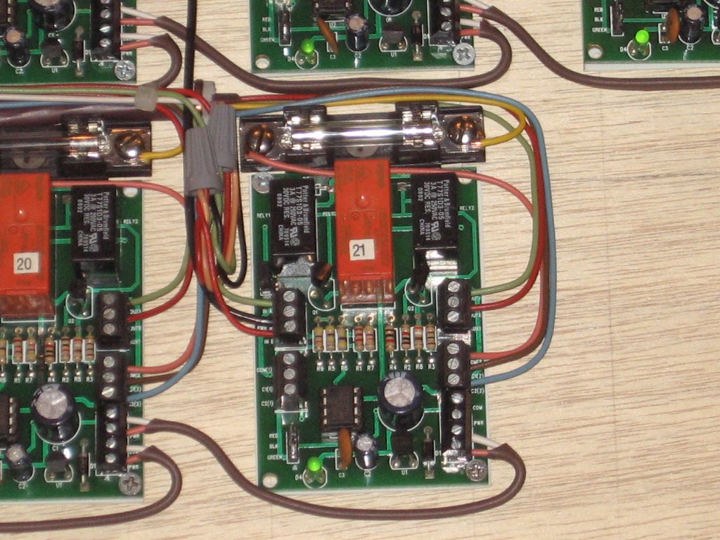
There is additional 3 amp track fusing associated with the Atlas 6924 relay board Power Routing systems. The 6924 relay boards are rated at 8 amps, but I was able to fry traces on these boards at the 7.5 amp track fusing pictured.  I went back to design and added 3 amp fusing to protect the 6924 relay board's Power Routing circuits.  Note that this (3 amp) fuse addition is shown on the Atlas website related to the 6924 relay board installation.  Click on the link posted.
Note the relay board Power Routing fuse (top of board).

Switches #17 and #18, (Cross over combinations),(note: numbers on relays and fuse blocks), require two track circuits for Power routing. Note: The two additional fuses to the right.

Power routing with O-54 and smaller switches is interesting.  Note that a lot of wheels pass through each switch via each train.  The Probability of a track short on the small, (normally dead rail), section of  a switch, (Now powered), is relatively high.  But if these (3amp) fuses blow, over all operation isn't neccessarily effected.  On occassion I visually check the fuses and replace blown ones.  Much easier and less costly that replacing 6924 relay board.  The relay boards and related wiring smooths out operation on a small layout, where a lot of switches are stacked relatively close.  IMO. A lot of head scratch'n on this project.  Mike CT

Last edited by Mike CT
Originally Posted by Mike CT:

Circuit protection. Fuses can be purchase at any auto parts supply.  The pictured fuse block will handle fuses and wiring up to 30 amps.  Model train circuit design usually requires much less.  There is quite an assortment of fuse sizes available.  I use 7.5 amp for track power supply and a lot of 3 amp fuses for accessory power.  In some case you may want to use smaller fuses.  Click on the underlined phrase to link a Grainger Supply detail page.  My experience, anything over 10 amps, a derail was arc/spark and welding. Grainger fuse selection chart (AGC fuses).

Thanks Mike!  Yes, this was exactly what I was thinking of.  Waytek Wire has a 12 pole (break-apart) version of this for $9.10.


George

Post
×
×
×
×
Link copied to your clipboard.
×
×