This stared out in a discussion on the LionChief forum that got pretty far away from the original topic being discussed. I thought it best to start a new topic to post what I've "discovered". The original thread can be found HERE.
Anyway,it came up that the manual for LionChief Plus engines states hat they should be powered by no more than 18.0 volts or they could be damaged. This was a non issue as the engine's owner was planning to use a Lionel transformer that would supply only 18 volts, however I commented that if higher voltages could damage the electronics of the engine, then caution should be taken with other manufacturer's transformers that are capable of supplying higher voltages.
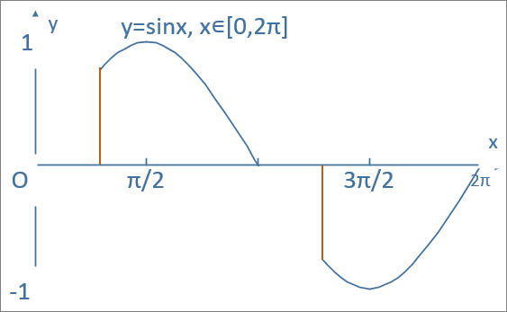
The premise is that with a so-called chopped wave transformer, the electronics of the engine will 'see' the full output voltage even when the throttle is set to a lower level. Because of this, electronics that could be damaged by higher than recommended voltages could be damaged even if the track RMS voltage is set to a lower level than the recommended voltage limit, because they would still see the full level that the transformer is capable of supplying.
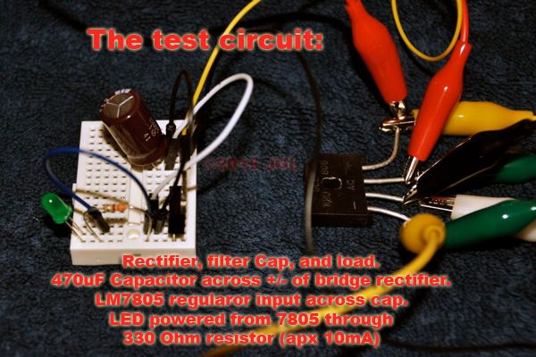
For my test here, I used a Z1000 with Zcontroller as my supply source. (As a side note, under even a tiny load this transformer would reach only 18.5VAC at full throttle, but without a load it reached 19.5VAC.) I constructed a simple circuit to mimic the circuit at work in almost all devices that convert AC power into DC. After opening up my LionChief Plus NW2 I can confirm that this engine used the same setup.
AC from the transformer is passed through a bridge rectifier which converts it into a DC current of varying voltage that rises and falls in time with the cycle of the incoming AC. A 470uF capacitor was then placed across the output of the rectifier to filter this pulsating current into a smooth, steady DC current. ( I can again confirm that the LC+ NW2 uses this same bridge and filter capacitor to produce the DC on which it operates. The NW2 uses a 1000uF capacitor.) From here I used an LM7805, an LED, and a 330 Ohm resistor to build a tiny load to drain the filter capacitor so that I could get better readings.
To measure and collect data I used two volt meters. I used my reasonably good quality meter to measure the AC voltage coming out of the Zcontroller. This meter measures true RMS, unlike the free meter I used for the DC measurement. A free meter from Harbor Freight was used to measure the DC voltage across the filter capacitor. This meter is not very good, but when compared to my good meter it reported DC voltages within 0.1 volt of the assumed true value, good enough to prove the concept here.
Here is the test setup:
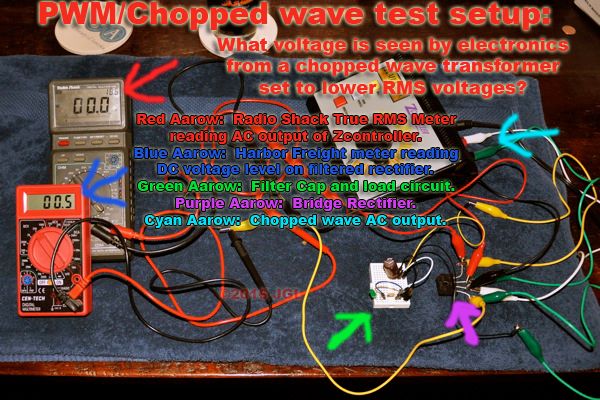
This setup fairly accurately mimics the bridge set-up inside my LC+ NW2. I repeated this test probing the connections on the engine's circuit board and found nearly the same results. The voltage reading were within 0.5 volts of what they are in the sample circuit. I tried to take some video of the actual engine being tested, but could not hold the probes on the board, adjust the transformer throttle and film at the same time. Suffice to say that the electronics inside that engine see similar voltages with the Zcontroller set to the same levels.
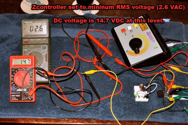
The experiment started by nudging the throttle up until any voltage was read on the transformer's output. It appears the Zcontroller kicks on at about 2.5 volts (AC RMS). Here at this bare minimum voltage from the controller we already read well over 14 volts DC being supplied.
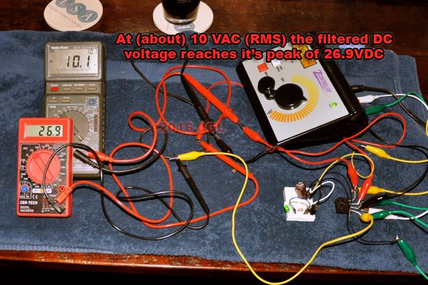
The DC voltage rises with the AC voltage up to about 10 volts (AC RMS). I suspect it is really closer to 9.75 volts, the half way point of the controller's full, no load, output. At 10 VAC the DC has reached 26.9 volts. After this point the DC voltage will rise no further. The filter capacitor is receiving a full half of the AC cycle, effectively receiving the same energy it would with a single diode under half-wave rectification.
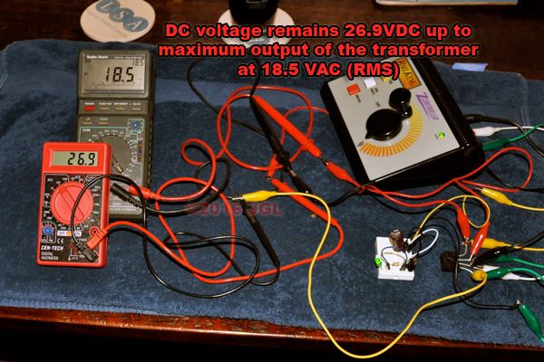
The DC voltage remains 26.9 volts as the controller is turned up to its maximum level of 18.5 VAC.
Here we have it in real time, a short, poorly lit video of the voltage readings as the throttle as it is turned up and back down. Aside from simply watching the meters, you can see that the green LED turns on the moment the Zcontroller is turned above zero and remains on until the controller is zeroed again. This is only of note because the 7805 regulator that powers it requires 7 volts DC to turn on.
The conclusion that can be reached is that the electronics running off of DC power inside your engines are going to see a significantly higher voltage than the RMS voltage of the AC would suggest. further, at anything past half throttle they will see the full, peak voltage the transformer is capable of providing. This means that the electronics must be capable of handling this peak voltage if you use a chopped wave transformer. A chopped wave transformer that is just turned down will still apply full voltage to the electronics.
As a side note, this is why I believe early ProtoSound locomotives do not work correctly on these 'chopped wave' transformers. They are designed to read track voltage with a simple AC to DC converter like this, and as such will never see low enough voltages to start up, the electronics read as if the throttle is at full when it is only barely turned up.
As a second note, I've been tracing out the boards of my NW2, and so far I've found nothing that could be damaged by less than 24 volts of full wave AC power. When I have a bit more information on that I'll post it over on the LionChief board. I am pretty sure that the electronics in any engine from one of the major manufactures will be just fine with 24 volts or less of full wave power ( < 35VDC peak voltage).
JGL


