I have a post war rotating flood light car with the vibrator. Running on command voltages the vibrator heats up quickly. Has anyone come up with a way to run this in command mode for extended periods without destroying it. Are the newer cars designed for 18 volts?
Replies sorted oldest to newest
A small voltage regulator board would allow you to set the voltage to the car lower than track voltage. Should be able to fit something inside the caboose body.
@RSJB18 posted:A small voltage regulator board would allow you to set the voltage to the car lower than track voltage. Should be able to fit something inside the caboose body.
Catch 22, you need an AC regulator, an entirely different animal than the typical and much easier DC regulator.
FWIW, the newer searchlight cars are using a pretty interesting and unique circuit- they are converting to DC, and then back to AC. Why? because Lionchief sets come with DC wall packs, and in the past, searchlight cars could not and did not work on DC, but with this circuit- now they can work on 18V AC or DC, because it's generating it's OWN AC.
Same thing seen in the newer DC capable Plug and Play searchlight towers
@Vernon Barry posted:That's because this is a plug and play version- thus compatible with DC 18V power packs from Lionchief.
So then you might be asking, wait, DC power, a vibrating style motor on the beacon, LED?
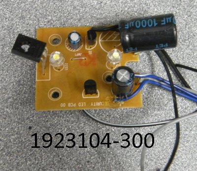
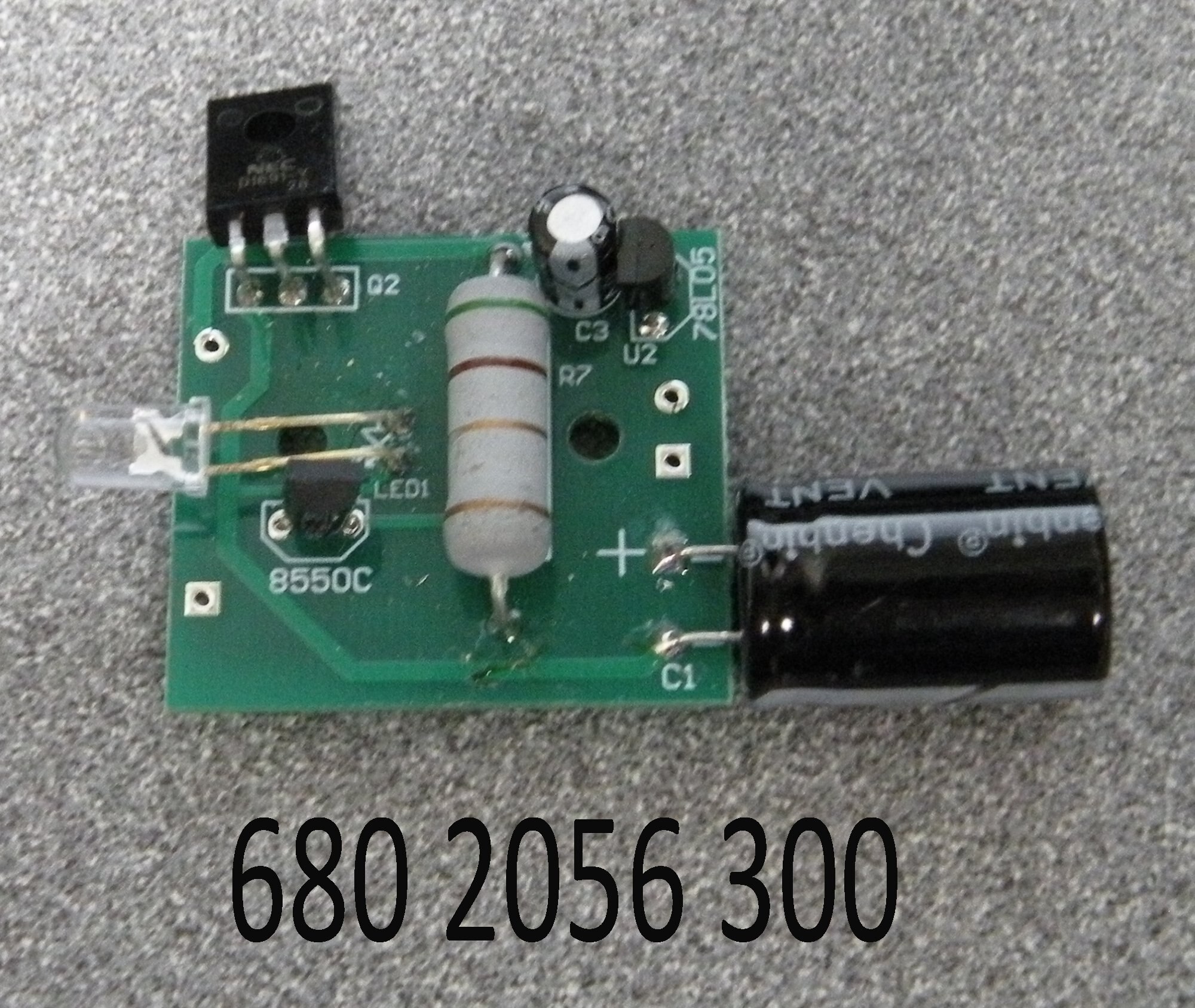
The PCB capable of creating AC for the magnet coil of the motor assembly, with DC coming in- just like many of the new searchlight "security" cabooses that you may have missed that came in the recent Army Lionchief sets.
https://www.lionelsupport.com/PCB-AC-DC-ROTARY-BEACON
PCB / AC/DC / ROTARY BEACON
Unfortunately they do not provide a picture of that PCB, however, here is a similar example.
https://www.lionelsupport.com/PCB-SECURITY-CAR
They are using a 555 timer and the 2SD882L to generate the AC from DC for the motor coil.
Similar PCB is also used in the Plug and Play operating freight stations
https://www.lionelsupport.com/...ng-Freight-Station_2
Again, the magic board- AC or DC to DC, and then AC again
https://www.lionelsupport.com/PCB-SECURITY-CAR

Attachments
@hokie71 posted:I have a post war rotating flood light car with the vibrator. Running on command voltages the vibrator heats up quickly. Has anyone come up with a way to run this in command mode for extended periods without destroying it. Are the newer cars designed for 18 volts?
I fully understand your concern and you definitely make a good point, the coil of the vibrating motor around the light will get hot at 18V.
Things one could do:
- put a resistor (big high power) mounted somewhere in series, however then the resistor is getting hot and burn risk.
- use diodes or rectifiers (with + and minus shorted together) in series to make a voltage drop- still gets hot, still is equivalent of resistor
- Use the electronic circuit method- although I'm not sure if the coil of an original searchlight- how that matches up to the new style coil with inductance/resistance?
A diode should be all you need, why are you looking at complicated circuitry?
Thanks for the ideas! I had a few minutes tonight to try the simple diode idea and the issue we could have guessed is half wave AC does not give a smooth movement to the vibrator. This is 16 volts RMS out of the transformer, through a diode, and to the track. I put my digital meter to see what it would read with this half wave rectified situation. You can see the bumpy rotation occurring.
$12 is a cheap board on the modern stuff.
@Vernon Barry posted:Again, the magic board- AC or DC to DC, and then AC again
https://www.lionelsupport.com/PCB-SECURITY-CAR
Attachments
2 diodes opposite polarity in parallel = voltage drop but both directions AC.
Or using a bridge rectifier and shorting + to - and wiring the two AC ~ terminals in series is the equivalent of 4 diodes, 2 in series in each direction.

I forgot about that thread. I have a few rectifiers and will give that a test in the next few days.
Way back when I worked at Skil, they had reactance chargers - no wall wart, the 120VAC from the wall was dropped using a non-polarized capacitor. During positive cycles the power would charge the battery thru a diode, and on negative cycles, I can't remember, maybe a resistor and a second diode. Can't be that simple, no way would that pass UL, and I know it was UL approved.
Deal is, you would need to have some idea of resistance and inductance of the vibramotor to pick the best cap. Or, just try one. Might be able to guestimate the L and R using an oscope, forgot how.
Remember, it has to be non-polarized! For instance, a motor start cap, or the caps you put on the brushes of a universal motor when converting to TMCC back in the day, only, probably bigger than that.
Finally got back to this project. As a starting point, I tested voltages and found that the vibramotor gets warm but does not "heat" up at 14 volts. This was a 30-minute test. I had several 3-amp rectifiers and tested three ganged together to reduce 18 volts to 13 volts. The rectifiers were not hot and the vibramotor was happy. This appears to be the solution I was looking for (especially since I have the parts I need). Thanks to all who responded to this thread and for the posters on the thread Vernon references below.
@Vernon Barry posted:2 diodes opposite polarity in parallel = voltage drop but both directions AC.
Or using a bridge rectifier and shorting + to - and wiring the two AC ~ terminals in series is the equivalent of 4 diodes, 2 in series in each direction.
Here is one of the rectifiers, they are small enough that several can fit under the generator in the empty interior.

Would you mind posting a picture of the finished circuitry?
Please provide the Spec's in the Bridge Diode,
Gosh I wish the local Radio Shack store was still around!
John N.
Did you try just a large capacitor to couple the AC signal into the coil? Any cap would do for a test, would probably take a cap in the 1uf and up range. All depends on how much current the coil is drawing at AC track voltage, and depending on cap size, may take more voltage to make it rotate than if the cap is not there. Worth a try anyway. If it does work, remember that 18VAC is RMS equivalent, and actual peak to peak is almost 51 volts, so pick a cap with a higher volt rating.
@john in western pa posted:Please provide the Spec's in the Bridge Diode,
Spec: 3A 400V (basically, any common rectifier with a 50V or higher rating)

@texgeekboy posted:Would you mind posting a picture of the finished circuitry?
@hokie71 posted:I had several 3-amp rectifiers and tested three ganged together to reduce 18 volts to 13 volts.


