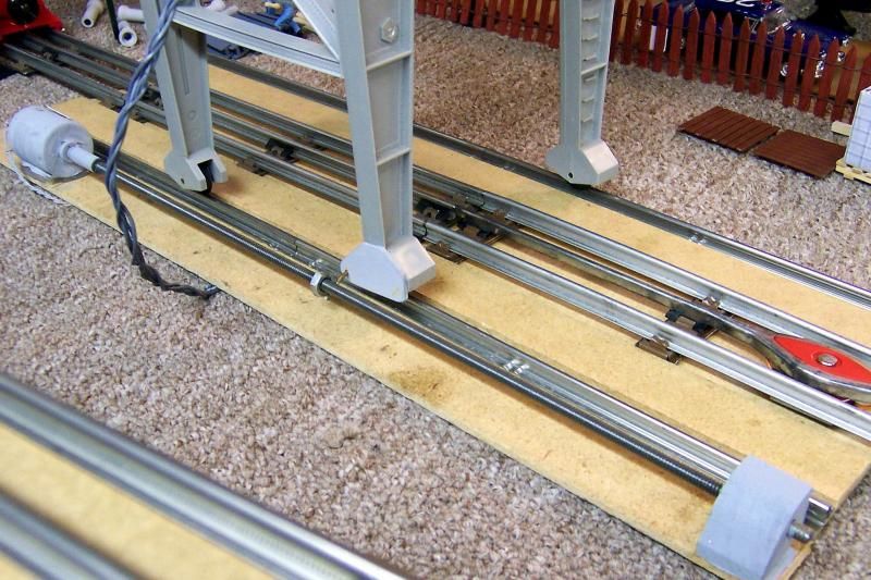
I just recently purchased a new Lionel Magnetic Gantry Crane and also the 37" GarGraves Track for Lionel Gantry Crane. I have been doing some research online and I found some videos that show moving the crane using a threaded rod. But what I am searching for is detailed instructions as to how to build it. I would like to know what type of forward/reverse motor would be the best choice. And since the track is 36" long I would like to use a threaded rod from 24" to 30" long for the project. I would think a 3/8" rod would work well. Plus a list of part needed to build the control unit and attaching the rod to the gantry crane base. 


Any information you can suggest would be greatly appreciated. 

Original Post

Replies sorted oldest to newest

I did one of these a few years ago. You can mount the mechanism either on top or below the table. I opted to mount as much as possible below the table to increase the illusion that it is self propelled. 3/8" rod is OK but the thicker the rod the stiffer it will be. A slight bend will cause a wobble. I had a few DC gearmotors I salvaged off old instruments. Voltage rating is flexible. The motor I used is rated for 36 volts but I am using 16 VDC. Speed is not an issue. You can find them for under 20 bucks on eBay. There are limit switches on both ends. They are SPDT with a diode on one side so after the switch is activated it can only run in the opposite direction. A DPDT switch is used to change direction. I tapped a piece of aluminum square stock and attached a piece of spring tempered copper to it. The copper sheet has a hole in it that clips onto one of the wheel axles that has been replaced with a longer one though a slot in the table. You could also operate it with a TMCC controller but as mine only gets used infrequently on our modular layout I haven't implemented that option. The Crane is TMCC but I found  response is very slow compared with using the switch controller supplied with the crane that I don't use that feature either. Its a big hit with the kids both young and old.


Here are some pics.


cranecontrolcrop


crane


y_crane


Pete

Attachments

Images (3)
  • cranecontrolcrop
  • crane
  • y_crane
Last edited by Norton

Many thanks for your input on this project. I really like the way you set up yours mounted under the table, but i will have to settle to have mine on top of the table.


Would you think a 1/2" threaded rod would work better than 3/8"'s. Because since I want to make the travel length for the crane 24" to 30" long since the GarGraves track in 36" long. I know on the motor end the rod will be supported well, but on the far end what can I use to support the rod so it will turn freely. I was thinking using a piece of wood to support the rod and putting a short piece of nylon sleeve over the rod with a nylon nut on the end. Then use a "U" shape clamp to hold it in place. 


I would also think that I would have to use two (2) nuts attached to the base of the crane platform to move the crane so it will prevent it from shifting on the rails. I would have to use a piece of metal brace and drill a hole for the rod to pass through and use a very strong glue to attach the nut.


If I have overlooked anything please point it out.

I actually used 5/16" rod but located where it is under the table the slot minimises the runout of the rod. Since you plan to mount the drive rod on top I think 3/8" might be the best compromise. Easier to hide. I thought I was going to have to attach the drive to at least two wheels but was pleasantly surprised that it ran true without crabbing using a single wheel. It takes little effort to move the crane so a simple screw attachment of the nut to a leg will suffice. I did replace the diecast wheels on mine with sintered wheels from a Post War 2046 Hudson engine truck. The repro parts guys sell these and they are the same size as the die cast ones. 

On my first version I supported the drive rod with ball bearings on both ends. The version shown only has the bearing on one and the other supported by the motor itself.


Pete

Last edited by Norton
Originally Posted by BFI66:
....or you can wait for Lionel's version being issued in 2015......i know you guys will believe it when you see it!

-Pete

That would be my option. I think if Lionel executes it right they may do well with the motorized version. People who hadn't given a gantry crane much though before might pull the trigger for one and find a place for it On their layout. I have to admit I may be one of them! 

Thanks for all the suggestions. I picked up a 3/8" rod which was 36" long. since I will be using the GarGraves Gantry Crane track which is 37" long. 

I think for my first try at this I will go with the rod on top of the train table. I just need to get the motor and make a control box and find a bracket to attached the nut to the rod.


And I do like the idea using another side track with the engine pulling the gantry crane.


The threaded rod above the layout is what I have been using for several years with excellent results.  A full construction article on how I did it appeared in the November 2009 issue of Classic Toy Trains.


You might be able to figure out how to make this fairly simple mechanism by taking a close look at the following picture.  12 volt DC motor from Radio Shack that is coupled to a 1/4" threaded rod using a flexible piece of plastic tubing.


Last edited by Rich Melvin
ROGER1 posted:

I approached that problem from a different angle......check out the photos and short video below and see what you think. A better use for my Plymouth than running around the layout, I thought.


Roger

IMG_0003

IMG_0006

I like this idea.  Is there anything special about the Plymouth or do you just run it like normal, and have to cycle it through a neutral in order to reverse the direction?

It works great. I also have a Porter to swap out there. Both are relatively tiny engines, so to me, they are perfect for this application. I have a knife switch to give power to it's track and find that with the accessory transformer (a KW) set to the appropriate voltage, I don't need to use the throttle handles on the KW. I just flip the small knife switch to cycle it's "transmission". 

And as you can see in the video.....there are actually 3 separated tracks. My inner loop, the switcher track and my outer loop. All three can be controlled to move freight cars or engines around to fine tune the swing of the crane. A crowd pleaser because you can get at least 2 people involved in a crane operation at the same time. One person operating the crane controls and another to move the consists around. Fun

Roger

ROGER1 posted:

It works great. I also have a Porter to swap out there. Both are relatively tiny engines, so to me, they are perfect for this application. I have a knife switch to give power to it's track and find that with the accessory transformer (a KW) set to the appropriate voltage, I don't need to use the throttle handles on the KW. I just flip the small knife switch to cycle it's "transmission". 

And as you can see in the video.....there are actually 3 separated tracks. My inner loop, the switcher track and my outer loop. All three can be controlled to move freight cars or engines around to fine tune the swing of the crane. A crowd pleaser because you can get at least 2 people involved in a crane operation at the same time. One person operating the crane controls and another to move the consists around. Fun

Roger

Thanks for the description.  Looks neat, and clever.  I've been thinking about getting a gantry crane for my new layout, and I happen to have a spare Plymouth.

Jeff,

The trick/challenge was the attachment to the crane. I initially had it attached to the legs, but the torqued it. I eventually came up with an aluminum brace between the legs and attached to the " generator trailer". So, any straight ahead motion of the engine translates into straight ahead for the crane. 

Roger

Several years ago a Forum member designed and sold a chain drive device for the Lionel gantry crane. It works great. I have an extra one I will sell for $100. Email me and I will email a copy of the instruction booklet to you so you  can  determine if you would like to buy the device from me. The same person also designed the original smoke fluid loader. 

ROGER1 posted:

Jeff,

The trick/challenge was the attachment to the crane. I initially had it attached to the legs, but the torqued it. I eventually came up with an aluminum brace between the legs and attached to the " generator trailer". So, any straight ahead motion of the engine translates into straight ahead for the crane. 

Roger

Thanks for the hint!  I wonder how it would do if you put the gantry crane wheels on a three rail track and pull it straight ahead by one of the legs?  Probably still torque.  I don't even have a gantry crane yet, but I like see stuff like this as it gives me some ideas as I move forward.

The one I did pictured above has the drive attached to only one axle. It does not torque. The difference may be due to the fact the its attached about as low as possible and also the stock die cast wheels were replaced by sintered steel wheels meant for 2046 pilot wheels available from the repro parts guys. The wheels are harder and smoother than the die cast wheels.

Pete

Add Reply

Post
×
×
×
×
Link copied to your clipboard.
×
×