I know it's something to do with the board because I put in another reverse board and the engine works fine.
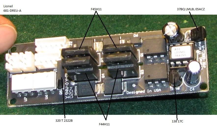
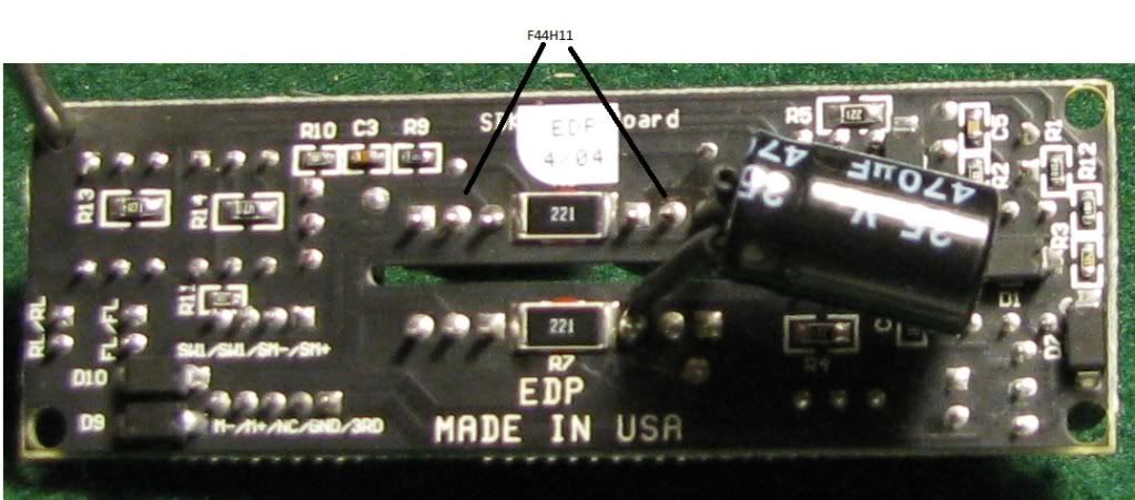
Here's a photo of the board with the numbers I copied from the transistors. Are these the likely culprits or is it something else?

|


|

Replies sorted oldest to newest
quote:Originally posted by stan2004:
What are you using to determine continuity?
Yesquote:
Something's off here. If both your NPNs are shorted, I can't imagine how it can work even in one direction.
I'm assuming the motor is disconnected when you made these measurements.
There is continuity between the two NPN emitters, likewise on the PNPs. I rechecked everything and I have continuity between pins 2-3 on both the NPNs. The PNPs check out fine, no continuity on pins 2-3.quote:Confirm there IS continuity between the emitters of the two NPN devices.
I don't think there's a separate rectifier off the board. The motors plug in directly to this board. Considering how cheap the transistors are I'll probably order one extra set of all of them, just in case. However, I like fooling around with my trains (chronic tinkerer) and learning how it works, or doesn't, which is simply another chapter in life on how to fix stuff. When I was a kid, I remember being fascinated by taking apart the open wound motor in my steam engine, cleaning and reassembling it. I suppose not much has changed.quote:gunrunnerjohn's idea to just be done with it and replace them all has merit. But if you want to tinker more, tolerate 20 questions, and explore the wonders of E-units along the way I'll try to help you. A photo of the bottom of the board would be handy. Is there a separate bridge rectifier off the board?

quote:Originally posted by stan2004:
So to be clear, with no motor connected, using Diode mode you measure each NPN between pins 2-3 (and then 3-2 backwards) and in each case you measure 0.0V (like when you touch the test leads together).
Yesquote:You do the same for the PNPs and in each case (pins 2-3 and 3-2) you measure "OL" or whatever the Fluke says when the test leads are not touching anything.
YEsquote:And if you measure, say, that diode on top of your pic of the burned K-line board you measure 0.7V (or so) in one direction and "OL" in the other direction.
Indeedquote:Let the games begin!
Here's the numbers 12C509A 04/P4K6 0351quote:Originally posted by Norton:
Disclaimer: Peal off the label and try and determine if its 555 type or microcontroller.
Pete
I do have an identical board. I'll tear into the engine that has it tomorrow and report back.quote:Originally posted by Norton:
You could verify if its that chip if you have and identical board. It appears to be in a socket so just swap them out.
Pete
DO you mean it will need to be disconnected from the board before I can do the continuity test?quote:Originally posted by GGG:
You can test the moc for continuity with a 5 volt test signal, but you will need to lift pins.
quote:Originally posted by iakobos:quote:Originally posted by stan2004:
So to be clear, with no motor connected, using Diode mode you measure each NPN between pins 2-3 (and then 3-2 backwards) and in each case you measure 0.0V (like when you touch the test leads together).
To be precise it's 0.6V black on 2, red on 3; and then 0L red on 2, black on 3
quote:You can test the moc for continuity with a 5 volt test signal, but you will need to lift pins.
Access to this requires an OGR Forum Supporting Membership
