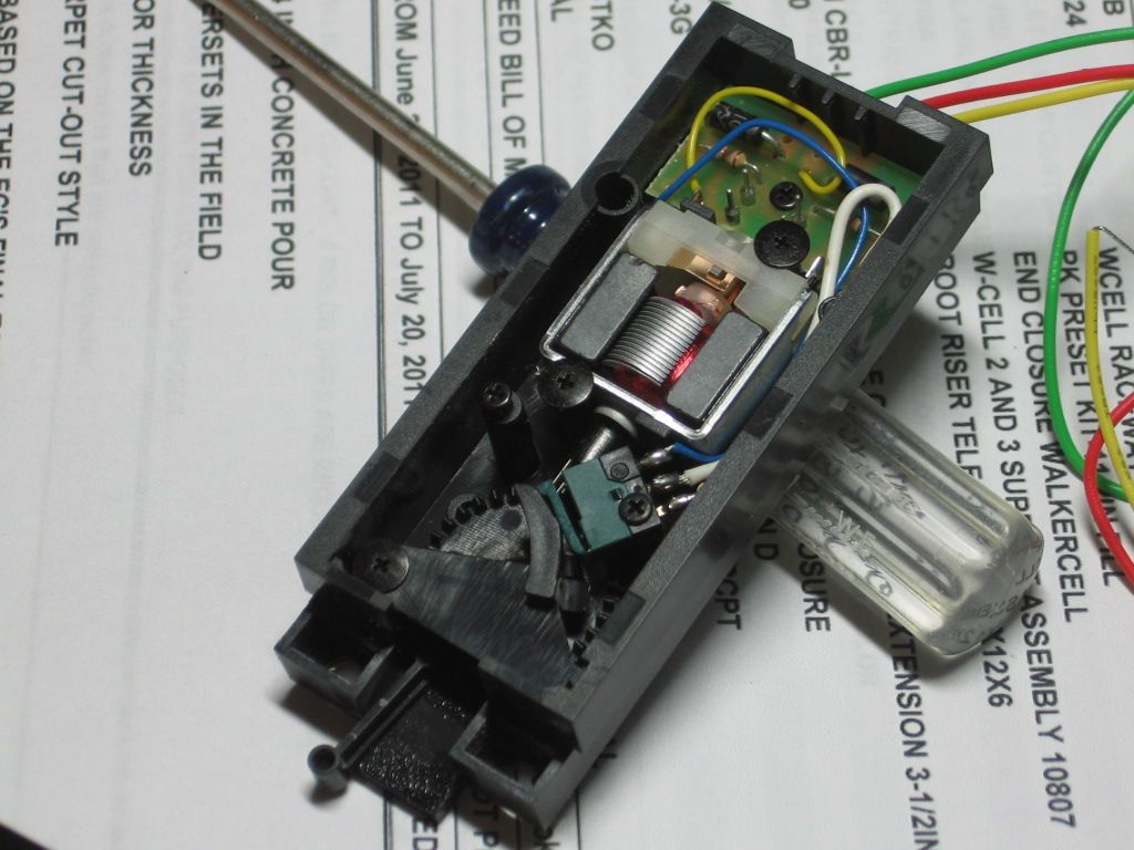
Troy, I assume you have short insulated rail sections you're using to throw the switch machine for non-derailing operation. If you wire these sections directly to the coil, you will burn it out after a while. Here is how to wire your NJI machines so that the switch machine only gets momentary power to throw the switch.
The NJI machine has 6 thin spring metal bands with contacts at the ends of them. You only want to use the inner 4 contacts for non-derailing as shown below.

Note that with the switch thrown in one direction, the contacts away from the machine (call them A and B) are closed and the contacts next to the machine (call them C and D) are open.

With the switch thrown the other way, the contacts next to the machine (C and D) are closed and the contacts away from the machine (A and B) are open. You can bend the ends of the contact bars A and D to make sure you get this opening and closing action.

To make it work, the wire from one of your insulated rails goes to a contact strip B and a wire goes from contact strip A to one of the outside terminals on the coil. The wire from the other insulated rails goes to a contact strip C and a wire goes from contact strip D to the other outside terminal on the coil. An A/C hot switch machine power wire goes to the center terminal on the switch machine coils. You can also see this wiring in the first photo above. The two capacitors are optional to decrease arcing in the contacts but they are a pain to solder into place and are not needed to make this work.

Troubleshooting:
1) If the switch machine doesn't throw when you roll a car across the insulated rails, reverse the connections of the insulated rail wires to the contacts. In the photo, if the copper wire was connected to contact B as shown, unsolder it and connect it to contact C. Move the silver wire to contact B.
2) If the switch throws the wrong way when you roll a car across the insulated rails (making it a derailing switch instead of a non-derailing switch), reverse the connections from the contacts to the machine coils. In the first photo, swap the positions of the silver and copper wires that connect to the outside terminals of the coils.


