Let’s imagine that you were looking for a Green and Red LED display that indicated the position in which your turnouts are thrown, straight-through or diverging routes. Which of the following displays would you like best? 


In each case,

• The first image shows how the display would look; i.e., neither Red or Green illuminated indicating that the points are not fully thrown in either position - a bad situation.

• The second image shows RED illuminated to indicate the diverging route.

• The third image shows GREEN illuminated to indicate the straight-through route.


(Click on images for larger size)


A. Single, bi-color LED. 

11 HES LEDs 1-Bicolor med


B. White LED's when off - then RED and GREEN

12 HES LEDs 2-Wht med


C. Standard Red and Green LED's.

13 HES LEDs Grn-Rd med


I must add that for the control panel my clear choice is the single, bi-color LED, as it takes less space.


Thank you for your participation!


Alex


Attachments

Images (3)
  • 11 HES LEDs 1-Bicolor med
  • 12 HES LEDs 2-Wht med
  • 13 HES LEDs Grn-Rd med
Last edited by Ingeniero No1
Original Post

Replies sorted oldest to newest

I like Option A, single Bi-Color LED, but I'm partial to that because that's what we used kinda. We went with a Bi-Polar LED with only 2 legs to wire much easier I thought. 1 LED as opposed to 2, less space, less wiring.


Prototypically speaking, mainline turnouts generally don't have indicators, unless a target in a yard, siding, or industry track. Mainline turnouts are indicated by block signals at a control point. 

Last edited by Former Member

So far 3 for A, one for C.


The single bi-color LED could be seen from the side if it were mounted as the others, which is very doable.


Wiring for B and C, with two separate LED's, would be just as simple as the single LED A because the B and C would be prewired resulting in three leads, the same as the single LED; i.e., one common lead, one lead for Red, and one lead for Green.


Thx!


Alex

Last edited by Ingeniero No1
Originally Posted by britrailer:

I like option A.


I've been trying to work out how to do this - can you post a circuit diagram and parts list?


The bicolor  LED's have three leads, as I mentioned in my previous post. Be aware, however, of which type you buy, which would be dependent on how you intend to drive the LED. There are two main types: Common anode and common cathode, and you have to decide what your source is (+ or -) for illuminating the green or red segment.


I have a non-contact method of detecting the actual and true position of the points and throwbar that is in no way connected or dependant on the switch machine or the its controls. I filed a provisional patent in March 2013, and the final, non-provisional patent application three weeks ago.


My non-contact points position detector does not add any mechanical load to the switch machine or its associated components. I have several installed on my layout, both on Atlas and RCS turnouts, and works great. I have displays next to the turnouts, a shown, as well as on the control panel. I will be ordering the first production batch in a few days. 


Thx


Alex

I too have Atlas switches and recently replaced all the Atlas switch machines with Tortoises's.  They not only look much better, but they operate much more reliably in my opinion.  Your LED's add a nice visual means of detecting the switch position which many people find to be very helpful.


Art

Originally Posted by N.Q.D.Y.:

I'm happy with any of the options, apart from those for the 'not fully thrown' position. In this situation I would prefer a flashing red light to alert me of a potential disaster. 

Nicole,

That is a good idea, indeed. However, the way they are now, at least on the control panel, an LED that is off is rather apparent. But I do like your idea.


For computer control the absence of a signal, neither green or red, would indicate trouble.


I have averted several 'accidents' when I have thrown a turnout and the LED did not change color! Why, you may wonder? Because there was an engine or a car 'parked' over the turnout! Of course, as soon as the train moves, the turnout can 'switch' and you may end up with a split train, or a derailment, or both.


Thx!


Alex

Originally Posted by Chugman:

I too have Atlas switches and recently replaced all the Atlas switch machines with Tortoises's.  They not only look much better, but they operate much more reliably in my opinion.  Your LED's add a nice visual means of detecting the switch position which many people find to be very helpful.


Art

Art,

The biggest issue is that most if not all of the linkages between the switch machines and the throwbars are flexible, which is a almost requirement to avert damage if there is a bind, as I just described above. Since my method is totally unrelated to the switch machine and instead reflects the actual position of the throwbar and points, will always provide the proper indication of the selected route, or if for some reason the throwbar and points were prevented from moving fully into either position.


Dominic,

"I have a switch on my layout where the straight branch is diverging!"

Yes, I have several like that as well. I asked once in the "Real Trains" forum, whether the green should be used for a diverging that actually means straight-through, and the answer was yes. And f course, you can wire the Green & Red LED segments to portray what you desire.


Thx!


Alex

So far:

A = 5

B = 1

C = 1


Britrailer,

"Great - I look forward to hearing how/where to order them.

Will you be posting details on the forum?"


Yes, I will offer them for sale in the forum, of course.


There will be two styles of detectors:

Type 1 for mounting on already installed turnouts, which will mount over the crossties.

Type 2 for mounting on turnouts that have not been installed, which will mount between the crossties under the turnout.


I will post pictures of the prototypes later today.


Thx!


Alex

Last edited by Ingeniero No1

Perhaps I will offer all three display styles, at the same price.


The detectors.

Over the past 1-1/2 years I have made about a dozen different detector styles by hand, and then had a dozen prototypes made with surface mount components for evaluation, which are the ones shown below. The production detectors will be about 1/2" x 5/8" for the top mount type, and about 5/16" x 3/4" for the bottom mount type.


The detectors require 12VDC, can supply up to 20ma, and no additional resistors are needed for the LED's - they are built into the detectors. The green and red LED's are wired with the Anode leads as common, connected to the +12VDC, and the other two leads (cathodes) for green and red are connected to the detector. The detectors have four wires: +12VDC, -12VDC, green LED, and red LED.


The magnets I use are 1/8" square x 1/16" thick (bottom mount), and 1/8" diameter x 1/16" thick (top mount). Yes, they are neodymium magnets.


TOP MOUNT:

I have a holder for the top mount magnet easier to install; it snaps in place and a drop of glue will secure it.


BOTTOM MOUNT:

The bottom magnet fits right in one of the square holes in the throw bar, and I simply glue it in place. (The turnout shown is one with which I experimented and is a bit butchered.)


I also have glued the magnets to the throw bar on RCS turnouts, mounted the detectors close to it, and they work fine as well. I plan to come up with an RCS-specific mount.


I'll let the pictures do the talking, and will be glad to answer any questions.


TOP MOUNT, suitable to be added on: (Click on the pictures for better detail.)   

14 HES-1A ThrwBrEnd med DSC07884


The magnet and the pin are flush with the holder top.

15 HES-1B StrtRoute med DSC07887

16 HES-1C DvrgRoute med DSC07888

17 HES-1D Module med DSC07890

18 HES-1E Detector Cvr med DSC07896


BOTTOM MOUNT:

19 HES-2A UnderMount-1 MED DSC07919

20 HES-2B UnderMount-2 MED DSC07919


Thank you for your answers, opinions and suggestions - all are great help!


Alex

Attachments

Images (7)
  • 14 HES-1A ThrwBrEnd med DSC07884
  • 15 HES-1B StrtRoute med DSC07887
  • 16 HES-1C DvrgRoute med DSC07888
  • 17 HES-1D Module med DSC07890
  • 18 HES-1E Detector Cvr med DSC07896
  • 19 HES-2A UnderMount-1 MED DSC07919
  • 20 HES-2B UnderMount-2 MED DSC07919
Last edited by Ingeniero No1

A. Bi-color LED.


Started out with C as favorite, but the more I compared the two (A & C several times), the more I liked A, it won out.  B never quite made the cut, it was eliminated in the 2nd round.


Your new device sounds very interesting to me also, will be watching for further information. 


Was reading further and I also like N.Q.D.Y.'s red flashing light idea. If that was possible, it would be a nice  feature.

Last edited by rtr12

Interesting thread, thank you for posting.  The Atlas 6931 dwarf lights (Red and Green) have a small PC board that requires power and a two wire connection to the switch motor/through and out terminals.  Apparently it works on the impedance of the two switch motor coils.  I added a small bases to the dwarf lights for more height.  There are modifications for multiple switch throws at the same time.  Diodes are added.  Some of the switch motor's impedance was not adequate for the system.  Atlas was replacing switch motors that would make the system work.  Noted by flashing dwarf lights between red and green.   Relatively expensive system. 

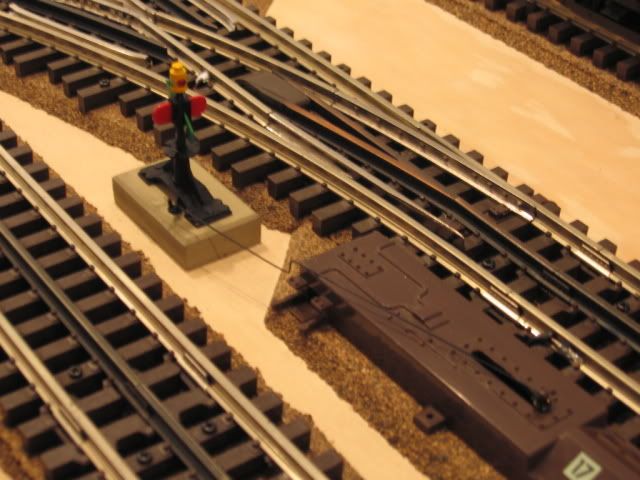
This mechanical connection to the switch motor worked well with this NJ International  signal.  Note the wire between the switch motor post and the signal. 

Last edited by Mike CT

PRICING

I am getting quotes for making the detectors in the U.S. as I can’t afford to make 1000’s as would be required to make them overseas. I will post my offering in the “For Sale” forum as soon as I find out.


In the meantime, I have to determine my cost for the three LED displays I showed at the beginning of the thread. I have not found any of them available as I showed them, at a reasonable cost, so all required some work on my part.


I also have to make the jigs for the magnet holder, which holders I make in my shop.


ATLAS

Mike,

Thank you for posting! That information is great.


I approached Atlas about a year ago and they were not interested because they told me that they already have such a system, as you mentioned. However, there is a big difference between the Atlas method and my method.


Atlas’ detector relies or senses the position of the switch machine, and as I said earlier, the position of the switch machine does not always correlate exactly with the actual position of the throw bar and points. You can block the throw bar and points, and the switch machine will still advance to the commanded position or route.


To reiterate, my method does not rely at all on the position of the switch machine or the command signals to operate the turnout. Instead, it detects the actual and true position of the throw bar, and hence, of the points.


Thanks!


Alex


PS. Here at home we are in a power outage - cables down due to wind. I am working on generator power.

Post
×
×
×
×
Link copied to your clipboard.
×
×