Unlike my usual “fait a complis” posts, this one is a work in progress. I will add to the thread as things evolve. In the interim, comments, criticism, and suggestions (both helpful and otherwise) are welcome.
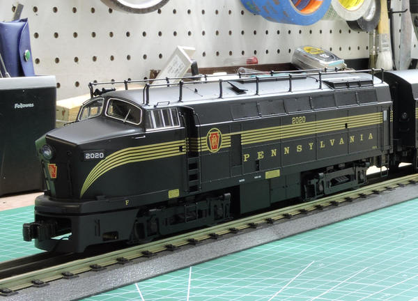
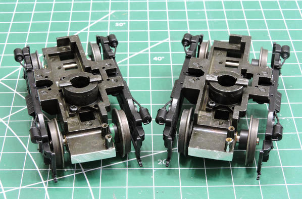
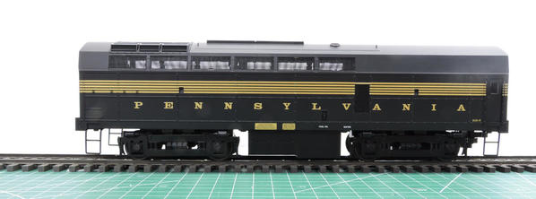
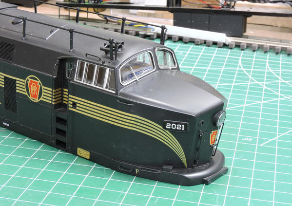
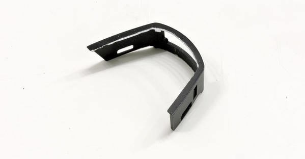
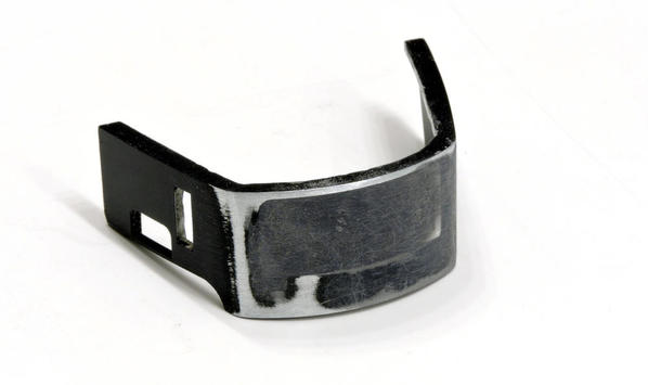
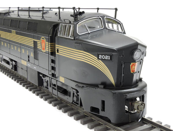
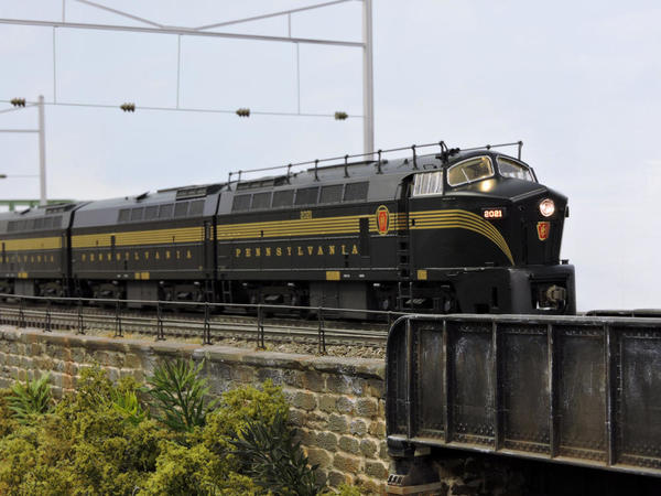
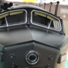
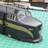
To summarize: Here is what I started with:
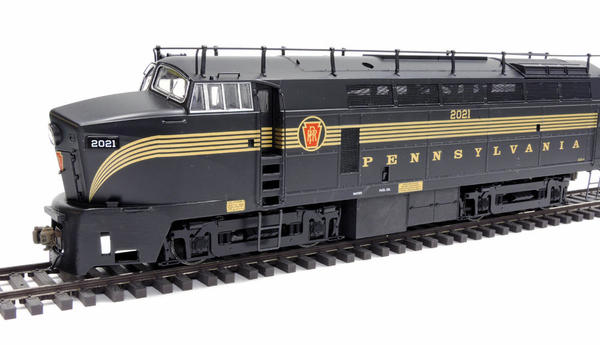
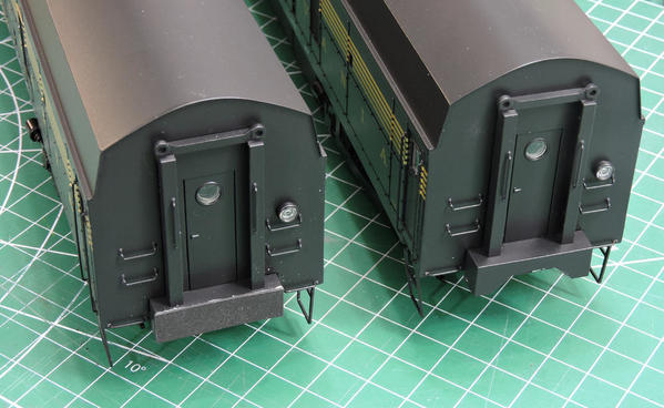
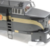
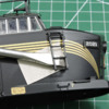
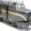
And here is my progress so far
INTRODUCTION: I really like the PRR sharks, particularly the as-delivered Brunswick green five stripe version. (The only PRR freight locomotives to have five stripes, by the way). They fit my layout time frame (1956 ish), but not my locale (Electrified main line). No matter, it’s my layout and I can do what I want.
Over the years, five different manufacturers have released models of the PRR Sharks. Here is my assessment:
Overland: Done in brass, with a single motor drive. This is the well established gold standard of the lot. They are prototypically accurate with all the details you could want. However an ABBA set will cost as much as a perfectly decent used car. And most of the ones I have seen for sale are missing lit number boards (if not the headlights), have suffered some ill fitting parts over the years, and lack sound (Yeah, I like that). All of which is fixable.
Lionel: A surprisingly good model. Yes the shells are made of ABS, and they have the much reviled twin motor drive with spur gears. But they are dimensionally correct and come fully painted and lettered. They have a lot of added scale size brass details such as grilles, grab irons, horns, trust and builder plates. And they come out of the box with a complete suite of lights, sound, and smoke. They also benefit from the precision that is inherent to mass production. One of the biggest (and most pleasant) surprises is the truck wheel base is almost spot on—it measures out to 9’9”. The Sharks had 9’10” wheel bases, which are considerably longer than most AAR Type B trucks. The longer wheelbase was necessitated by the larger Westinghouse Traction motors. These were unique to the Sharks, and kudos to Lionel for getting this right!
MTH: Have a diecast body that is again close to spot on dimensionally. It’s a bit narrower than the prototype but its only 3”. So who would notice. Certainly not me. Like the Lionel, it comes fully painted and lettered with a full complement of lights and smoke. I had an ABBA set back in my three rail days and they were among the best runners I had. Also like the Lionel, they have excellent, scale sized body details, wire grab irons, and etched body grills. They also have see through fans. The AB units are tethered together, and the tether is big and obvious. Not an intractable problem, but it would still need to be solved. The bigger problem however, is the trucks: They measure out to only an 8’4” wheel base. Now before you pen your indignant post about me being a Uber-SPF. That is a whopping 3/8” too short and really obvious. As MTH took the pains to get the wheel openings right, the thing looks like a C7 Corvette running on a space saver spares.
New Jersey Custom Brass; In my opinion the details on these are down several notches from the three listed above. They are 2 rail (a minor plus for me) and their brass construction has all the usual advantages that allows such as a lighter look and thin window openings.
Weaver: These are available from the factory in 2 rail. They are scale size, and the truck wheelbase is close enough at 9’4” (The standard length of an AAR truck with GE Traction motors). But the models are almost totally devoid of any added detail.
So I selected the Lionel.
PLANNED MODIFICATIONS: I wanted to build the RF-16 Version (That’s BF-16 in Pennsy talk). I used two references:
“Pennsylvania Rail Road Diesel Locomotive Pictorial, Volume Four—Baldwin Cab and Transfer Units”. By John D. Hahn. Published by Withers. This has 21 pages devoted to the BF-16 sharks alone. About three times more pages are devoted to the other Baldwin Sharks: The BF-15 and the BP-20.
The Keystone Modeler, #93, Summer 2015. There is a review of the prototypical sharks, and a review of the BLI HO scale Sharks for comparison. The latter was actually useful!
Based on these references, these are the things I have done/will do
- Convert to 2 rail (new wheels and pickups)
- Lower per above referenced post
- Move truck sides inward
- Improve appearance of side screens
- Kadee 745 Couplers (using Mario’s mounts), except the front of lead A unit which is Protocraft
- Shorten non-prototypical rear porches, to allow much closer coupling between units.
- Add fully detailed and full size cabs in both A units. To make room for it in the powered A, I moved the lead motor into the dummy B.
- Add sunshades
- Removed the truck mounted steps, and added body mounted steps under the cabs
- Remove the nose ladder, the grab irons in front of the cab, and the step on the pilot. This backdates the locos to my era. Plus it looks a whole lot better
- Reconfigure the front coupler opening in the pilots
- Fix the pilots so they are integrated into the shell. I both eliminated the horizontal seam and painted the pilot to match the shell. This captures the massive “hunk-of-steel” look of the prototype.
- Add cut levers to the pilots (requires opening the cast in hole)
- Add an air hose and chain to both pilots
- Add a speedometer cable to the front axle of the front truck
- Add MU hoses between the units
- Change to warm white LED headlights.
- Weather and detail paint
I got a head start because of the excellent post started by Norm Charbonneau on lowering and adding Kadees to the Lionel sharks:
https://ogrforum.com/t...-16s-anyone-ever-mod
Many contributed to that post. An example of the OGR forum at its best.
Also, I would be remiss if I did not specifically thank two OGR Forum members:
Norm, who measured the truck wheel bases for me, and told me that not only did Lionel get the Brunswick Green right, it’s a dead match for Polly Scale Brunswick Green.
Mario (Central Fan), who provided me with his 3D printed Kadee coupler mounts. These fit right in place. They are predrilled threading 2 mm holes, and they are the right thickness so the couplers are at the correct height after the units are lowered.
So with that as an introduction, here we go:
OPERATING SYSTEM: I run DCS on my layout. I had originally intended to convert these to DCS as well. However when I got these sharks and applied conventional AC power to them, I found I much preferred the Lionel sound set to those of my former MTH sharks. So I bought a Lionel Cab1L system, and now run Legacy on my layout along with the DCS.
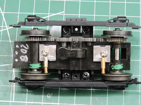
TWO RAIL CONVERSION: I took the lazy path and gave all the trucks to Joe Foehrkolb convert. He uses NWSL wheels, and for the insulated side uses pressed in and drilled out Micarta rods. (Stephen Bloy did a similar thing when he converted his Lionel sharks to 2 rail, but used a different insulator.) Since I was dealing with eight trucks that looked the same but were in fact different, I color coded all of them so I would know where they go, which way they faced, and which side should be insulated. Joe said he appreciated that last one.
For the pickups, I used my standard plunger tube technique. The three rail pick ups are disassembled, and only the base plate kept. Brass tubes are soldered to the base plate, and then a brass escutcheon that is soldered to the next smaller brass tube is the contact. A NWSL spring is used to keep contact against the inner wheel face. Note the current contact is through the sliding brass tube, and that the spring only provides the contact pressure. I have been using this arrangement for years and have yet to have a contact fail.
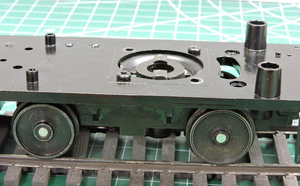
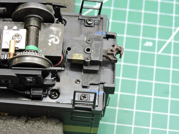
LOWER: I used the technique that was pioneered by Norm (see the reference to the post above) and is now fairly common. Move the lock plate to the top of the chassis:
Before:
After:
MOVE TRUCK FRAMES SIDE INWARD: I have done this on many diesels, and credit Mike Pitogo with the original idea. Using a drill, I slot the mounting holes in the truck side frames so they sit closer to the wheels.
You also have to cut off the locating pins, and file back some of the “ears” on the trucks. But its an easy job. Without going through too many heroics, you can move the frames in about .060”. This may not seem like much, but now the brake cylinders are inside the sides of the body, and the stance, especially viewed from head on, looks more realistic:
IMPROVE APPEARANCE OF THE SCREENS: The sharks have many screens: a horizontal row along the top of the car body, a vertical one behind the cab, and a set on the radiator section. Lionel did a great job making these from etched brass. But then they went on to ruin the effect on the horizontal and side screens by placing a piece of white styrene behind them. Fortunately this is an easy fix. The screens pop out, as do the styrene pieces. Toss the styrene, and then pop the screens back in. You will have to bend the mounting tabs a bit, as well as touch up some chipped paint. But they look far better:
As you might imagine, some wire management inside the shell is called for so you can’t see some non-prototypical antenna wire through the screens.
ADD KADEE COUPLERS: I used the pre drilled mounts provided by Mario (Central Fan). They work great. I tap the existing holes for 2mm thread and the Kadees mount right in. I hold the pads with a combination of Walthers Goo and Gorilla Super Glue Gel. This is my go to method of producing a very strong bond that has a little bit of compliance. They aren’t going anywhere. For added strength against pull out Mario designed the pads at the back end of the A units and both ends of the B unit (they are the same) to interlock into the porch section of the shell, like this:
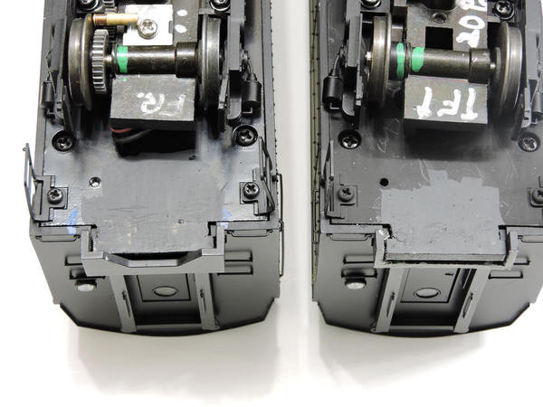
I did not like the resulting gap between the units. This is not Mario’s doing, its Lionel’s. Lionel has a rather large back porch at the back of their units. It is not prototypical, and it prevents the units from getting close. It may be an artifact of the three rail coupling. So I cut off about .100” off the porch and added a .010” piece of styrene to close it off.
This enabled me to move the couplers further inward:
Here are photos of the gap with the couplers fully extended
BEFORE
AFTER:
I established that these will easily go around 40” curves (that’s 080 to some of you).
My guess is it will do tighter than that.
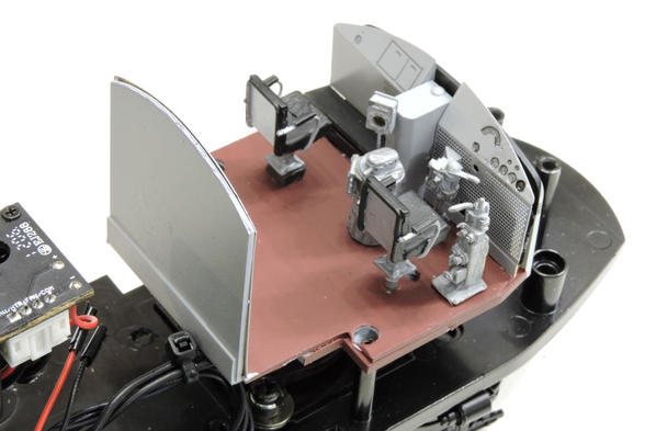
ADD FULL CAB INTERIORS: The Lionel provided cab interiors are a bit frugal. (I am being somewhat generous here). And it’s not just because the rear of the cab is encroached upon by the motor. Some, like Mario, have improved the cab significantly with paint and details. I chose another course and built up a full cab using parts from the P&D Hobby F unit cabs. I kept the Lionel floor and dashboard to serve as a substructure, but I completely cut off the semi cylindrical back that surrounds the motor. I made a full floor and back wall using .080” thick styrene sheet.
In the photo above, the original Lionel interior is black, the new floor and back are white styrene, and the assembly is being held in place while the glue fully cures with magnets to a right angle steel block. In this manner I retained the Lionel floor mounting points and dashboard location, so I could be sure everything would fit in place.
Here is a photo of one view of the new cab. The P&D kit contains some very nice photo etched brass and cast brass details. The colors are appropriate for a PRR F unit.
Here is a photo of the other view (the gap between the top of the dashboard and front wall are not visible when the shell is in place.)
And here is the original Lionel offering
On the Legacy units the cabs are lit when the loco is called up. The cab light goes out when the loco starts to move. A nice effect:
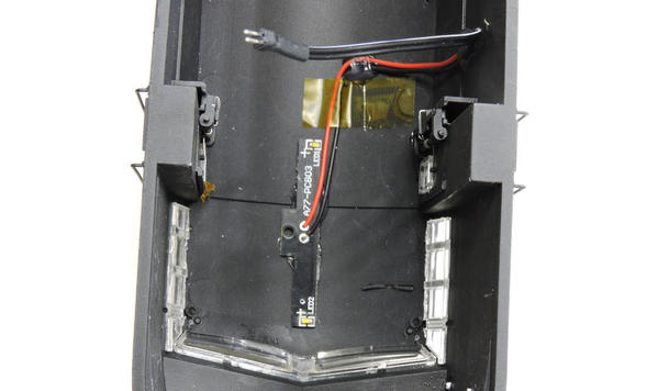
Originally the cab light was attached to the underside of the roof of the semi cylindrical back wall. Since I cut that wall off, I had to reposition the light to the underside of the cab roof:
And attach the wire to the control electronics through a Minatronics 2 Pin Micro Mini connector (Part # 5000102 ). This allows the shell to come completely off.
The photos above are for the trailing dummy A. For the powered A, I plan to do the same thing, except I will have to move the lead motor to the front of the Dummy B unit. I will use the same type of 2 pin Connector for that. They are small and can be made fairly unobtrusive.
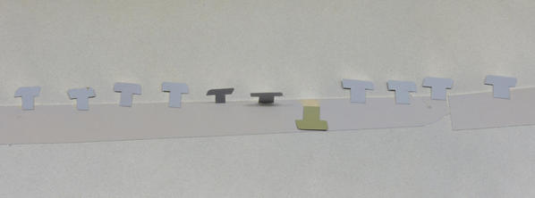
SUN VISORS. After wasting a lot of time trying to get the P&D sun visors to work, I decided to make my own from phosphor bronze. Here they are finished and painted:
Here they installed from the underside of the cab:
And here is what they look like from the front:
CAB STEPS I removed the steps from the front trucks of the A unit. I ordered a set of rear steps from Lionel, and installed them to the shell in the front. The only tough part is I wanted to hold the steps in with a screw for durability. I drilled and tapped a hole in the shell, but you don’t have too much material to work with before you break through the top of the lower most step on the shell. The screw ended up being really short, about 3/32” long:
REMOVE NOSE LADDER AND GRABS IN FRONT OF THE CAB. Lionel chose to add nose ladders and grabs to the nose on the right side of the cab, as well as a step on the pilot. This was required by Federal law in 1959. That is after my era, so these have to go. They also ruin the smooth lines of the nose, which is the real reason they need to go. Oddly enough very few five stripe Sharks ended up with these ladders, as they had been repainted with a single stripe before the ladder was imposed. Hahn’s book shows only one! Even more oddly, Lionel’s D&H and NYC Sharks do not have this ladder.
Removing the ladder and grab irons is easy. Insert a flat blade screwdriver under the part and twist. A piece of cardboard protects the paint:
Look closely, and you will see that Lionel left the original grab iron in place at the top of the ladder. That would not have happened in real life, but is a gift here as I did not have to install one. If you do it right and you are lucky, you can expose clean mounting holes. Find the next size up styrene rod. Drill the former mounting holes out to the diameter of that rod. Insert the rod, and wick Tenax 7R or other suitable styrene cement from the back side. Slice the protruding rod flush with a really sharp razor blade. Paint. This is what you end up with:
The hole vestiges will be hidden by weathering. The pilot also has a step on the right side. The step screws in, so just unscrew it.
I will take care of filling in the pilot in the pilot vacated by that step a little later
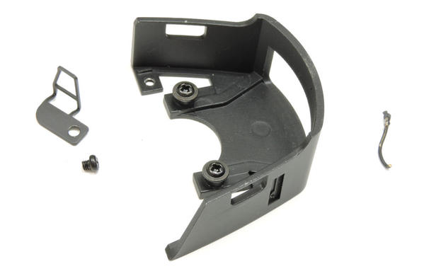
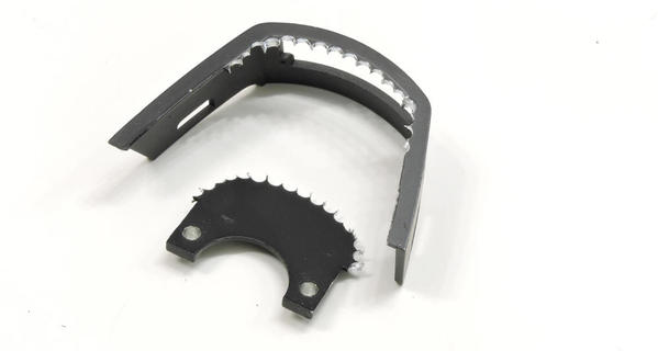
FIXING THE PILOT, PART I. As written above, I wanted the pilot to be a big massive seamless affair, per the prototype. Unlike the Weaver BP20, in which the seam is where the pilot meets the body, the Lionel pilot is split in two parts. One is attached to the shell, the other is supposed to swivel with the truck. So you can’t just mounting the pilot to the chassis, as the seam would show. You can’t just fill the seam with putty, because you could never take the unit apart. So the only choice is the hard way, where the chassis is cut back so the pilot can be mounted directly to the shell. And that is what I did
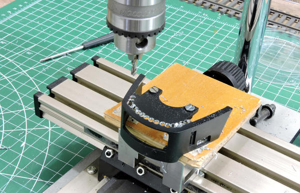
The first step is to remove the center web of the pilot. I mounted it in a drill press and drilled out a series of holes:
I then held the pilot against the chassis (with the shell mounted) and traced a clearance opening:
After several heart stopping moments with a jig saw, the chassis was cut back
PILOT MODIFICATIONS: Before mounting the pilot, I had to fix the coupler hole. Looking at Hahn's photos, there were many variations on the coupler hole as shops were continually modifying them. Rectangles of all heights, tees with vertical legs of all heights (including all the way through to the bottom of the pilot), and truncated tees were all popular. In Hahn’s book I did not see any BF-16 with coupler doors. I chose one that looked like this:
I figured it was interesting looking with out being too difficult.
The first step was to fill the opening with .080” styrene, bent under a heat gun, and then held in place with Gorilla Glue Gel Super glue:
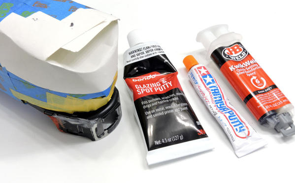
I then filled it with JB KwikWeld and sanded it smooth
After wielding a jewelers saw and some files and it looks like this
Note I opened up the cut lever holes in the side of the pilot. They were just cast in impersonations of a cut lever.
MOUNTING THE PILOT. I quickly realized that this is one of those things you have to get right the first time. Further compounding the problem is that the pilot is not an exact match for the shell (it’s a bit narrower), so you have to pick carefully where the mismatch is. To gain a small advantage, I built a jig to clamp the pilot while the glue dries:
I glued the pilot with JB Kwik Weld. I put a light even coat on the edge of the shell, pushed the pilot into position, aligned it, and then tightened the screws on the jig. I then wiped the JB Wkwik weld across the joint. You have about 2 minutes to do all this. So a rehearsal is recommended. (JB says six minutes to set. I find you really only have two).
When the JB had fully cured, I built a bridge of JB Kwik Weld across the seam on the inside. After that had cured, I added a fillet to fill the opening vacated by the step.
Finally, I went through several iterations and puttys to smooth out all the joints and imperfections.
Note the shell has been masked of above the pilot during this entire process. By the way, I really did not want perfection here, particularly in the front. I figured it would indicate the pilot had done its job
I primed the pilot with Rustoleum Dark Gray primer, and then painted it with a 50:50 mixture of Polly Scale Brunswick Green and Clear flat. I find the clear flat adds much needed binder to the paint. I add a drop of dawn, spray in light coats, and then over coat with Testors Semi Gloss.
The match to the existing paint is pretty good!
Again I sort of like the dents, and if I decide I don’t, I can take care of them by weathering
AIR HOSE ON PILOT
There is nothing wrong with the Lionel provided air hose. But it had to get pulled out when I reconfigured the pilot opening. I discovered much to my amazement that the brass hose is quite brittle, so bending it was a problem… I had to patch it with JB Weld along the way. I am not that happy how it looks in close up. But this is the trailing A, so it won’t be as visible.
The chain is simply some blackened chain I had in my scrap box.
So as of right now I have finished both the powered and dummy B, and am almost finished the dummy A.
Stay tuned………..


