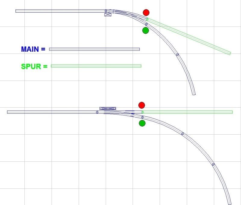
A turnout may be used to divert traffic from a main line onto a siding or spur, for example. For through traffic, the points are thrown straight or normal, and this direction is indicated by green. To divert to the siding or spur, the points are curved or reverse, and are indicated by red.

What is the proper terminology and colors if the turnout is on a curved portion of the main, and to continue on the main, the points are thrown curved, and to divert to a siding or spur, the points are thrown straight?

Would it be called normal and depicted by green to stay on the main even if the points are thrown curved?

Thx!

Alex
Last edited {1}
Original Post

Replies sorted oldest to newest

First things first on the question. I'm guessing a little at your meaning, but I think you're referring to a switch in a curved portion of a mainline. That would imply a curved switch in the same sense we use them in O Gauge to save space and ease transition into the interior of our layouts.

IF that's what you're asking then the answer is, "curved switches" as such in the prototype world are rarely encountered. Maybe in an industrial or terminal situation or unloading loop or something of the kind. But I don't think it's something you'd likely see.

On the other hand, IF you're asking in the prototype world does the branch ever take the straight and the normally straight ahead take the curve, I do believe the answer is yes, but it's disfavored and done only when there's no choice. And btw the term "mainline" has I think been described in several ways, but one way (and I don't recall where I heard it) was, it's the normally straight ahead track, and that helps explain it.

Anyway, your lights would be arranged accordingly. In which case, you then have the additional question what kind of signalling system is involved, diverging or other. But, I'll have to leave that part of the issue for the prototype guys here.
I am interested in the experts opinion also. I have that situation where my yard lead track starts. I tried to avoid it but the alternative seemed worse. My guess is that for signalling purposes, the curved route for the mailine would be the top signal. For control panel purposes, I currently have the green for the straight route (yard lead) and red for the diverting route (mainline).

Art
Here are the two cases I have on my layout.

1. Curved switches (RCS) where the the wider curve leads to a spur

2. Straight switches (Atlas) where straight points leads to a spur

As follows:


I added the "Red" and "Green" indicators according to what I believe you said.

Comments?

(BTW, the reason I am asking is that I am ready to start installing the toggle switches on my control panel to operate the turnouts. Also, now I want to make sure I get the DCS Remotes to show the proper direction according to the function and not just according to the direction of the points.)

Thx!

Alex
Last edited by Ingeniero No1
From the way you stated your question, I think you want your signalling to mimic the prototype. But, for the reasons I mentioned above and because there is more than one signalling system and because you only have red and green available, then imo neither of your examples match up to prototype usage or lend themselves to that. So I'd go with normal toy train diverging signalling and let both spurs take the red, as you've proposed. In other words, I think you're doing it just fine.

In the toy train world, ANY thing we come up with that makes sense or is consistent to the individual operator, is correct.
Very simply stated:
On my control panel, I have one bi-color LED at each turnout. These LED’s will turn GREEN or RED depending on how the points are set.* Obviously, it is up to me whether to make them turn RED or GREEN, which is the reason for this thread.

Therefore, should I wire the LED’s so they turn GREEN when the points are set so the train remains on the main or mainline, and turn RED when the points are set for the train divert to a siding or spur? I believe the answer is yes. Let me know.

(*) I have finally come up with sensors that sense the position of the points, so the LED’s do not display the last command issued to the turnouts, but the actual direction. And if the points are not fully thrown, the LED’s will not be lit at all.

When I get done, the turnout LED colors on my control panel will mean:
Green = Points set normal – proceed straight through.
Red = Points set reverse – divert to siding or spur.
Clear /Off = Points are not fully thrown – go see what the problem is
Orange (both Green and Red) = problem with sensors – ditto.

Thanks for your help!

Alex
I have 14 switches on my layout. Two of them lead to yard tracks when in the straight position. So to keep on the main the two switches are normally in curve position. I signify this by green. When all the controllers show green I know the train is staying on the main. To have 2 controllers red "for main" would be too confusing.
I don't know if this really pertains to switches but we have a Septa train line that runs behind the plant where I work. They have light signals over the track and the Green lamp is on top and the Red lamp is on the bottom.
I would venture to guess that the green is go or as I stated above "High-Ball" and the Red means to stop.

If a train is entering a siding the engineer would have to know that there is a stop ahead and Red would be the color to signify that. A Green lamp would mean to go full speed.

All I can say is that on the MJM green is the main line. Of course the exception to that rule is when a train enters a siding then turns to exit that siding back to the main line via another switch. Then the auto throw cercuit will set the switch to Red to allow the train to pass back onto the main line.

So I would say the on my railroad the MJM all switch paths that permit a train to pass onto, or off of a siding are in the RED position.

As Alex shows in his drawing above if the main line path is on the turn side of the switch then so be it, the turn direction gets the Green lamp. This is because that becomes the High-Ball path.
quote:
Originally posted by Ingeniero No1:
...should I wire the LED’s so they turn GREEN when the points are set so the train remains on the main or mainline, and turn RED when the points are set for the train divert to a siding or spur? I believe the answer is yes. Let me know.
The answer is YES.

In the real world, the red and green lights on a turnout/switch are not used to indicate which way the points are set. They are used to indicate which ROUTE is set. If the Diverging Route of the switch routes the train on the main line, then the switch indicator light should be green when the switch is set in the diverging or reverse position.

Some of you are mixing terminology in your answers. Alex is asking about the indicator lights on a switch stand, not overhead track block signals. The various aspects that overhead signals might display is a completely different subject.
quote:
Alex is asking about the indicator lights on a switch stand. . .

Rich,
That is correct.

As a matter of fact, right now I have the bi-color LED's mounted next to the turnouts; that is, the ones I have completed and I which I am testing. When I finish the the control panel, I will be 'moving' those LED's to the track display on the panel.

Thx!

Alex
quote:
Originally posted by Bobby Ogage:
By the logic Green = mainline, then at a mainline junction all indications are green? I don't think so. I suspect that green vs red on the mainline is up to a particular railroad.


Hi Bobby, if you have two main lines that cross, as they do at a cross track and you have GREEN in all directions something is wrong. THis is because one of the trains would have to have a STOP signal or there would be a crash.

OH where is Rich when we need him? Big Grin Oh thank you Rich I read your post after I read Bobby's. Roll Eyes
Post
×
×
×
×
Link copied to your clipboard.
×
×