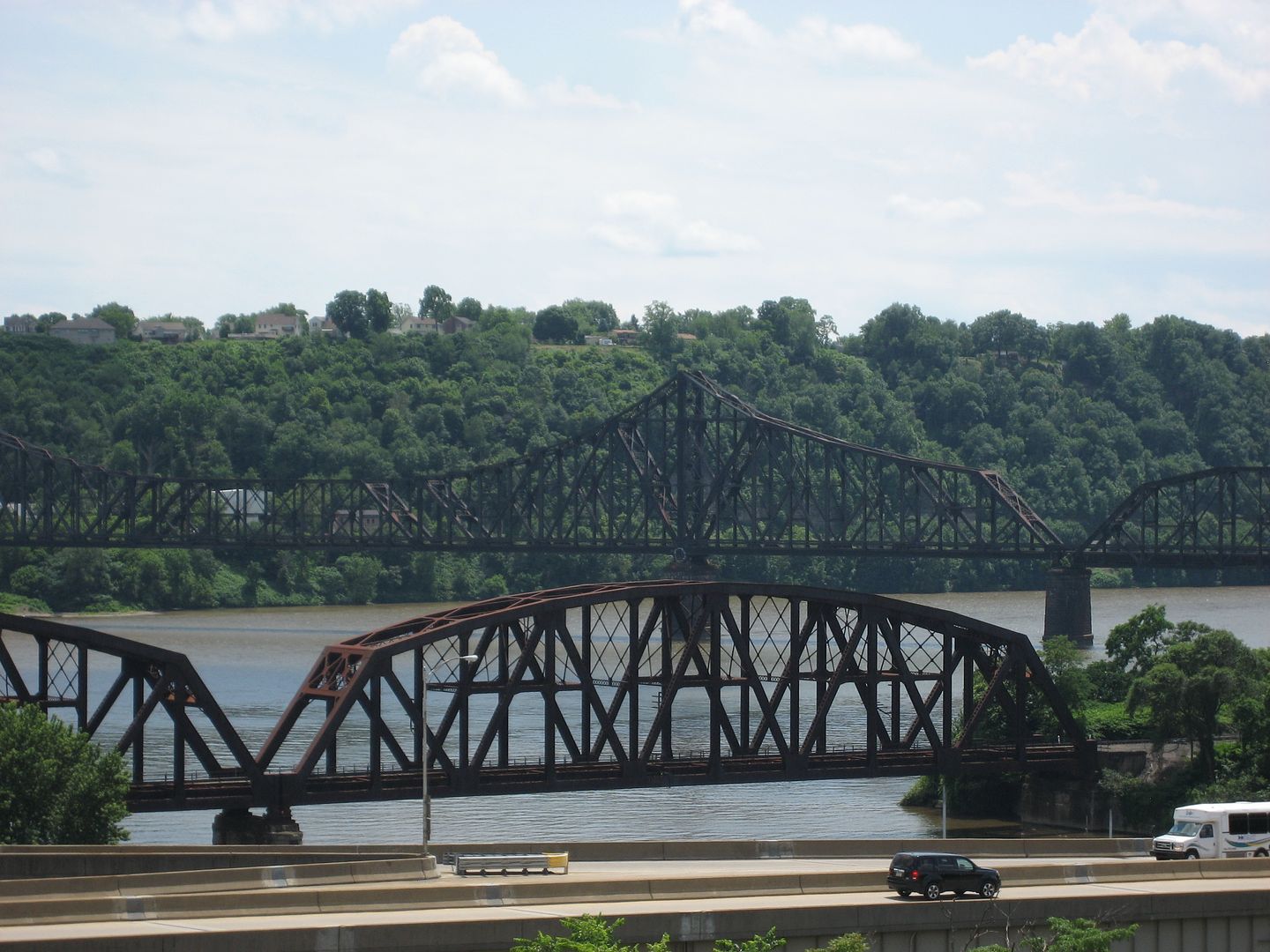
Whenever I happen to pass by any railroad related property, I am in awe of the effort railroads went to to build things that last.  The thread on the tunnel under the Hudson reminded me of this.  The Pennsy, NYC, Reading and most other Northeast railroads built things to last.  

Think about the catenary systems of the Pennsy and Reading Railroads.  They're approaching ninety years and still serving the present owners well.  Most of the suburban stations that are on Septa property are still standing.  Although Septa has done an outstanding job of building new structures adjacent to the old ones.  

And think about this.  Trains rumble through day and night.  All of that action and the infrastructure has held up rather nicely.  

Just my own observations.

Original Post

Replies sorted oldest to newest

About 20 or so years ago; Procor was building aluminum sodium chlorate hoppers for us at their Oakville, ON site.  I visited the plant to see some of the cars in different stages of production.  These chlorate cars had some similarities to a stub sill tank car in design with one major difference being the materials of construction (aluminum vs carbon or stainless steel).

While there, one of the Procor engineers showed me a computer animation of the buff and draft forces encountered by these cars while moving empty in a train and it was, to say the least, eye opening.  These cars were actually designed to flex in a manner somewhat analogous to an accordion although not as extreme, of course.   

The draft gear on carbon or stainless steel tank cars absorb some of the buff and draft force but; the shell of the car must still be designed and constructed in such a manner as to allow some buff and draft to transfer from end to end without causing the weld seams to crack.

Curt

Kelly Anderson posted:
rattler21 posted:

I cannot imagine the stress on frameless tank cars being slammed in a classification yard. 

I believe they have frames, they are just on the inside.

Kelly; they do not.  A stub sill design is just that.  There is no longitudinal sill or frame on a stub sill car.  The body of the car is intended to substitute for a sill or frame.

Curt

I did a quick Google search Railroad Tank Car structure, same result as Curt.   By 2025 all DOT 111 tank (cars) are to be retired for a newer, more robust, tank (DOT117) More (thicker) Metal.  (I think, if I remembered all that correctly).   Reference was made to Bakken Crude Oil, a shale oil abstraction, that is much more volitile and corrosive than most crude oils, an evolving (tank car) transportation problem.     

Last edited by Mike CT
Mike CT posted:

I did a quick Google search, same result as Curt.   By 2025 all DOT 111 tanks (cars) are to be retired for a newer, more robust, tank (DOT117) More (thicker) Metal.  (I think, if I remembered all that correctly)   Reference was made to Bakken Crude Oil, a shale oil abstraction, that is much more volitile than most crude oils, an evolving (tank car) transportation problem    

Mike; the 111’s must be retired from flammable product services by that date but may still be used for non-flammable products.  

The DOT 117 design has 9/16th inch thick steel in the shell along with full height head shields to make the ends more resistant to puncture.  The 117’s also have to have thermal insulation between the shell and the jacket to prevent flammable products from ”cooking off” if the car is in a derailment and a fire breaks out.  Bottom outlets must be protected by a skid plate and top fittings must be in a protective housing.  

We just took delivery of a bunch of 117’s last fall and it is a much more robust car design than the old 111’s.  More expensive too, I might add.  (And please, no one ask “how much”.  That info IS confidential and divulging it would constitute a “career decision”.)

Curt

TexasSP posted:

One can't discount the intensive maintenance required for all this infrastructure though. That has to account for a good bit of it too.

True.  And think of the amount of infrastructure there once was, compared to what is left now days.  When I ride Septa, into town, there are still, believe it or not, vestiges of sidings, albeit rotting away, along the line.  There used to be more, but most have been removed as part of Septa's improvement program.  

juniata guy posted:
Mike CT posted:

I did a quick Google search, same result as Curt.   By 2025 all DOT 111 tanks (cars) are to be retired for a newer, more robust, tank (DOT117) More (thicker) Metal.  (I think, if I remembered all that correctly)   Reference was made to Bakken Crude Oil, a shale oil abstraction, that is much more volitile than most crude oils, an evolving (tank car) transportation problem    

Mike; the 111’s must be retired from flammable product services by that date but may still be used for non-flammable products.  

The DOT 117 design has 9/16th inch thick steel in the shell along with full height head shields to make the ends more resistant to puncture.  The 117’s also have to have thermal insulation between the shell and the jacket to prevent flammable products from ”cooking off” if the car is in a derailment and a fire breaks out.  Bottom outlets must be protected by a skid plate and top fittings must be in a protective housing.  

We just took delivery of a bunch of 117’s last fall and it is a much more robust car design than the old 111’s.  More expensive too, I might add.  (And please, no one ask “how much”.  That info IS confidential and divulging it would constitute a “career decision”.)

Curt

I used to be an ARI shareholder. I’d have called investor relations and asked the list price of a 286k 117 car.

Dominic Mazoch posted:

BNSF did some testing on the original bridges in the Abo Canyon when it was widened to 2 Main Tracks.  All were good.  About a century old.  And only has to think of the tonage thrsr bridges held.  Plus the "pounding" by syeam power.

Well, contrary to popular belief, steam locomotives of the modern era do NOT "pound the rail". During the operational of former C&O J3a 4-8-4, renumbered to 614T, on the Chess System, the FRA instrumented a section of track between Huntington and Hinton. Over many, many weeks of 614T handling loaded coal trains eastbound, and empty hopper trains westbound, consistently the 614T exhibited less track/rail stresses than the current diesels operating over same section of instrumented track. Imagine THAT!

Back in my working days as a structural engineer I was involved in Conrail's clearance improvement project for double stack containers. I was in a meeting with Jeff May who was Conrail's chief structural engineer one time and asked him why their minimum thicknesses for structural steel plates was 4 times what is typical in other design codes. His reply was, we know we are not going to maintain it so we make it 4 times larger than it needs to be.

I think that turned out to be wise as equipment and loads were only going to get larger over time.

geysergazer posted:

This because 614 didn't achieve anything like the adhesion factor of contemporary AC-motored high-adhesion-trucked computer-controlled locomotives. AC traction motors bring new meaning to the term "controlled slip" (wherein maximum adhesion is achieved with about 10% wheel slip).

Lew

The adhesion factor has NOTHING to do with wheel rail loadings, i.e. the actual weight of the wheel on the rail as related to Cooper Ratings for bridges.

Last edited by OGR CEO-PUBLISHER
Hot Water posted:
geysergazer posted:

This because 614 didn't achieve anything like the adhesion factor of contemporary AC-motored high-adhesion-trucked computer-controlled locomotives. AC traction motors bring new meaning to the term "controlled slip" (wherein maximum adhesion is achieved with about 10% wheel slip).

Lew

The adhesion factor has NOTHING to do with wheel rail loadings, i.e. the actual weight of the wheel on the rail as related to Cooper Ratings for bridges.

and weight-of-the-wheel-on-the-rail has nothing to do with lateral loadings ("pound the rail") produced by poorly balanced steam locomotives. The 614 was well balanced. "track/rail stresses" is a broader term which (I assumed) includes rail-head wear. Please correct me if I'm wrong in stating that railhead wear rates are higher with SD90MACs than were the case with...the 614. Isn't that what you were saying?

Last edited by OGR CEO-PUBLISHER

Hot Water, you make a clear distinction of the differential concerning adhesion and loading. 

My open question is:  In response to adhesion, I am guessing the description of the responsive horizontal force or pressure of the  rail being encouraged to move rear ward as the locomotive's wheels are working to roll forward would be compression while the rails in front of the locomotive would be under tension.

How real is this speculation?

I have no real RR experience and would appreciate a respectful response.


Tom Tee posted:

Hot Water, you make a clear distinction of the differential concerning adhesion and loading. 

My open question is:  In response to adhesion, I am guessing the description of the responsive horizontal force or pressure of the  rail being encouraged to move rear ward as the locomotive's wheels are working to roll forward would be compression while the rails in front of the locomotive would be under tension.

Must admit that I do NOT understand your question. First, any "horizontal force", or Lateral Forces, would generally be on curved track. A key factor in some derailments is when the Lateral Forces exceed the Vertica,l or down, Force, i.e. the "L over V".

How real is this speculation?

Again, I don't understand your question nor your theory.

I have no real RR experience and would appreciate a respectful response.


HW,  Sorry.  Poor choice of words on my end.

When someone places a rubber mat under a tire stuck in the snow, the tire usually spits  the mat out due to the torque of the drive wheel. 

Conversely, when an loco is starting to move forward, theoretically, it would seem to be "spitting the rails" so to speak,  rear ward.  Of course there is both attachment clamping retention and skin friction on the tie plates augmented by vehicle weight.

I am wondering what level of compression/movement would be in the rail under that situation.

Typical modeler over  thinking the situation.

Last edited by Tom Tee
Tom Tee posted:

HW,  Sorry.  Poor choice of words on my end.

When someone places a rubber mat under a tire stuck in the snow, the tire usually spits  the mat out due to the torque of the drive wheel. 

Conversely, when an loco is starting to move forward, theoretically, it would seem to be "spitting the rails" so to speak,  rear ward. 

No, otherwise the locomotive and train would not move forward.

Of course there is both attachment clamping retention and skin friction on the tie plates augmented by vehicle weight.

I am wondering what level of compression/movement would be in the rail under that situation.

Just my opinion but, there better be NONE, otherwise the rail would break.

Typical modeler over  thinking the situation.

Hmmmmmm.


If you consider a diesel locomotive, the (electric) traction motors apply a torque to the axle of a wheel set. Torque is the product of a force and a distance - for our purposes pounds times feet or lb-ft. When a torque is applied to the axle, a friction force is developed between the (two) wheels and the rail. The friction force is equal to the applied torque divided by the radius of the wheel - and is the tractive force developed by the wheels. When torque is applied to the axle (and wheels), the surface of the wheel tends to slip rearward over the rails. This causes a forward-acting friction force (traction) to be developed on the part (bottom) of the wheel in contact with the rail, and an equivalent rearward-acting force to be developed on the rail (Newton's law - action and reaction.) The rearward force on the rail causes it to push rearward against the ties and ballast,  which exert a forward-acting force on the (bottom of the) rail and prevent it from moving. This again is the application of Newton's law - action and reaction. Lateral force acts in a sidewise direction across the rails and is generated by the wheel flanges contacting the sides of the rail. Sorry for the lengthy explanation but it explains what's happening.

As for vertical forces imposed on the rails by a steam engine, a portion of the weight (constant force on a smooth, level rail) acts downward on the rail where it is contacted by each driving-wheel. In addition, there is a once-per-revolution (sinusoidal) vertical force due to imperfect balance of the driver and connecting-rod masses. The balance is never perfect, so there always is an unsteady vertical force acting on the rails in addition to the constant vertical force due to the weight. There also are higher harmonic vertical forces (twice-per-revolution, three-times-per-revolution, etc.) but these become smaller with each increasing harmonic. I again apologize for the lengthy explanation but I'm just trying to contribute to the discussion. There's no avoiding the fact that it's technical.

I have been considering doing a detailed analysis of the rail forces created by a steam engine and posting it on the forum but not sure if it would be of interest to readers.

MELGAR

Last edited by MELGAR

Thanks, seemed well explained.  The imperfect balance you mention,,  in theory the chassis assembly has a designed in balance to it.  I am guessing your out of balance is that lack of perfection where the designed balance failed to meet perfection. 

Were steam engine chassis run in stationary to discern fine balance?

Additionally, as with propellers and rotary blades, each assembly has it's own band of harmonic balance distortion.  Something perhaps, engineers know best which particular steam engines zones to either void or run through quickly.


Tom Tee posted:

The imperfect balance you mention,,  in theory the chassis assembly has a designed in balance to it.  I am guessing your out of balance is that lack of perfection where the designed balance failed to meet perfection.

The balance at issue is the combined balance of just the rotating parts - driving wheel, eccentric crank and connecting rods - not the balance of the entire locomotive. If the center-of-gravity of the combined wheel, eccentric crank and connecting-rods were exactly at the rotational axis of the wheel, there would be zero dynamic vertical force (due to mass imbalance) at the rail when these parts are in motion. In actuality, perfect balance cannot be obtained, and the combined center-of-gravity is not exactly at the rotational axis. The effect is like whirling a mass at the end of a string. As the mass rotates around in a circle, the centrifugal pull varies in direction - and always points to the outside of the circle. If the mass is exactly at the center of the circle, there is no centrifugal force and no variation of force at the rail due to mass imbalance.

The other important effect on vertical force at the rail is the tension/compression force in the (main) connecting-rod. During one revolution, the force in the rod varies from compression to tension as steam pressure is alternately supplied to each side of the piston - first causing it to move rearward (compression in the main rod) and then forward (tension in the main rod). When the eccentric crank is in a downward position and the piston is moving rearward, the compressive (thrust) force in the main rod is angled downward and pushes downward on the eccentric crank which produces a vertical force component that acts downward on the rail. When the eccentric crank is in an upward position and moving forward, there is a tension force in the main rod which pulls downward on the crank, also resulting in a downward force on the rail. During one revolution, the piston starts in the forward position with zero downward force on the eccentric crank. A downward force acts on the eccentric crank (and downward on the rail) as the piston moves rearward. When the piston reaches its rearmost position, the downward forces on the crank and rail are zero. A downward force again acts on the eccentric crank (and downward on the rail) as the piston moves forward. When the piston returns to the forward position, the downward force is again zero. Therefore, during one revolution of the main driving wheel, the vertical force at the rail due to piston thrust goes through two cycles and sets up a second-harmonic vertical (downward) force. The mathematical analysis is complex and was more difficult to do accurately in the days of steam and before computers.

MELGAR

Last edited by MELGAR

Melgar,  I like your thinking and the manner in which your express yourself.

Coming from a high performance background I am very familiar with dynamic balancing with piston/pin/rod&throw aspects. 

Kinda smiled when you thought I was referring to finding the center of balance  which we had to pull for aviation pre flight.  That would require one mean seesaw and fulcrum for an Iron Horse.

My comments only covered  the rotating mass and inertial effect of the attached reciprocal components.  In theory there should not be any pounding of the rails with true in balance condition and a properly quartered driver. 

My only experience with an out of balance condition was when a piston skirt failed on a lightened assy. Nasty.  But what does a motor head know about real trains?

mark s posted:

It was said the original Penn Station was built to last a 1000 years. Alas, it did not last 100, due to the perfidies of finance and taxation in this society. On the other hand, Starruca Viaduct in Pennsylvania, built by the Erie RR in 1848, is still in use.   

Penn Station was not torn down because of taxation, it was torn down because the Pennsylvania Railroad was financially in a hole, and were desperate for ways to get a cash inflow. They basically sold the site of the station, which was lucrative because of air rights above the station, to developers for quite a bit of money. The public sector role was there was no such thing as a landmarks preservation law at the time, plus there was quite a lot of pressure applied politically to let this project go through, the building trades were in a slump in the early 60's, plus there was the ego of the developers of the site and those who wanted to build a new MSG.  That doesn't mean Penn Station was in perfect shape, because of the Pennsylvania Railroads post war decline, a lot of maintenance was deferred and the station needed work. 

Interesting topic, infrastructure and how long it lasts is based on a number of things. Certainly, a poorly built structure or whatnot is likely to become such a maintenance burden that it gets torn down and replaced, there have been plenty of examples of this, things like the infamous Flxible bus that was put on city streets it wasn't designed for, subway trains like the Zephyr that were difficult to service. Other things were designed to do something and didn't end up doing what it was supposed to, like the S2 turbine.  

A lot of infrastructure is lost because it simply is no longer needed, a lot of the rail bridges and stations and track were abandoned, for example, of signal towers were made obsolete by more modern technology. Other infrastructure is lost because despite how well it might have been made, it was marginally needed and cost too much to maintain to justify its existence.  

One of the ironies of looking back and saying "how well things were made back then" is that many of us grew up in a time when infrastructure was starting to fall apart, and assumed it was because modern infrastructure and the like was inferior, when the reality was a lot of that was older infrastructure, built to pretty high standards, that had been let go or not maintained well, anything no matter how well (or poorly designed), that isn't maintained starts falling apart, the only difference is the rate and timespan when it falls apart.

You don't paint bridges and clean them, they start corroding and falling apart, you don't maintain track bed, replace rails (especially on curves), you have problems, you don't replace parts on an engine or train car when you should, it fails. The other thing about old guard construction is it was often overbuilt because they didn't have quite the knowledge of engineering we do today, they would overbuild bridges because they didn't really fully understand the stresses and loads on it, things like aerodynamic loads, hydrodynamic loads from flowing water, vibrational issues, were fully understood, and in many ways modern structures, built with modern materials, likely will take less maintenance and be more durable than some of the older buildings and structures and the like. Not to mention that back when those things were built, labor and materials were a lot cheaper than today, so they could afford to overbuild.

It is kind of like comparing modern road building to the way Romans built their roads, the Romans built to a depth of 16 feet in many places with all kinds of sub bed materials, and a lot of those roads have lasted into modern times, 2000 years later; the reason they built them like that, in part, was because they had a lot of guys in the Roman army they needed to keep occupied, when not fighting a lot of the Roman army was acting as a corps of engineers, so it was a perfect combination

Add Reply

Post
×
×
×
×
Link copied to your clipboard.
×
×