Hello,

I have an MTH floor layout that has been working fine with a partial inner loop with two switches. I recently completed the inner loop with a four switch crossover. I know no longer get power to the inner switches (switch blocks do not light up) or track.

I know I'll need to add more power lock-on points along the track, but I'm not sure if I can with the DCS Explorer. I'm waiting on a WTIU, but now I hear they won't be available until next year.  Also, I cannot fit the switch blocks on the outer switches anymore because the track is right up against the wall and there's not enough room between the tracks for them to fit.

I'm using all MTH Realtrax, a Z-1000 power supply and DCS Explorer.

I wondering if someone can tell me if I might have a connection issue or the switch configuration does not allow power to the inner loop.

Thanks for the help,

Cyril

MTH_Room_Fill_Loop

Attachments

Images (1)
  • MTH_Room_Fill_Loop
Last edited by CyrilW
Original Post

Replies sorted oldest to newest

You don’t mention what track you are using, but I don’t think that is your problem.

What are the yellow dots in your plan?  If those are insulators they are in the wrong place.  If you want the loops separate, the insulators should be between each of the switches in your crossovers.  Also, you need a power connection to your Explorer for the inner loop.

"I know I'll need to add more power lock-on points along the track, but I'm not sure if I can with the DCS Explorer"

You can add as many lock on power entry points as you want. You only have one power and signal source so as long as they all connect to that source you are fine. Again, you have a single source, that is not a problem in and of itself being a single source. What is potentially a problem is the limitations of the DCS Explorer box as far as DCS signal strength, but also power limitations. Remember, you power trains, not track. If you build 2 loops to run 2 trains, you are possible attempting to be powering 2 trains at the same time from a single source. What matters is the load of the combines trains and cars you are intending to run. Your Z1000 brick can easily exceed the limit of the DCS explorer as far as amperage and depending on a fuse to save your bacon from a derailment or overload short typically ends with a dead DCS explorer. By the time the thermal breaker in the Z1000 brick trips you might have damaged or blown the fuse in the DCS explorer. The Z1000 has a 6A thermal breaker

Again, to use proper distribution, use something like the MTH https://mthtrains.com/50-1014 or larger https://mthtrains.com/50-1020

You would just be connecting the red and black terminal output of the DCS explorer into the below distribution block, and then from the distribution block to multiple lockons around your track.

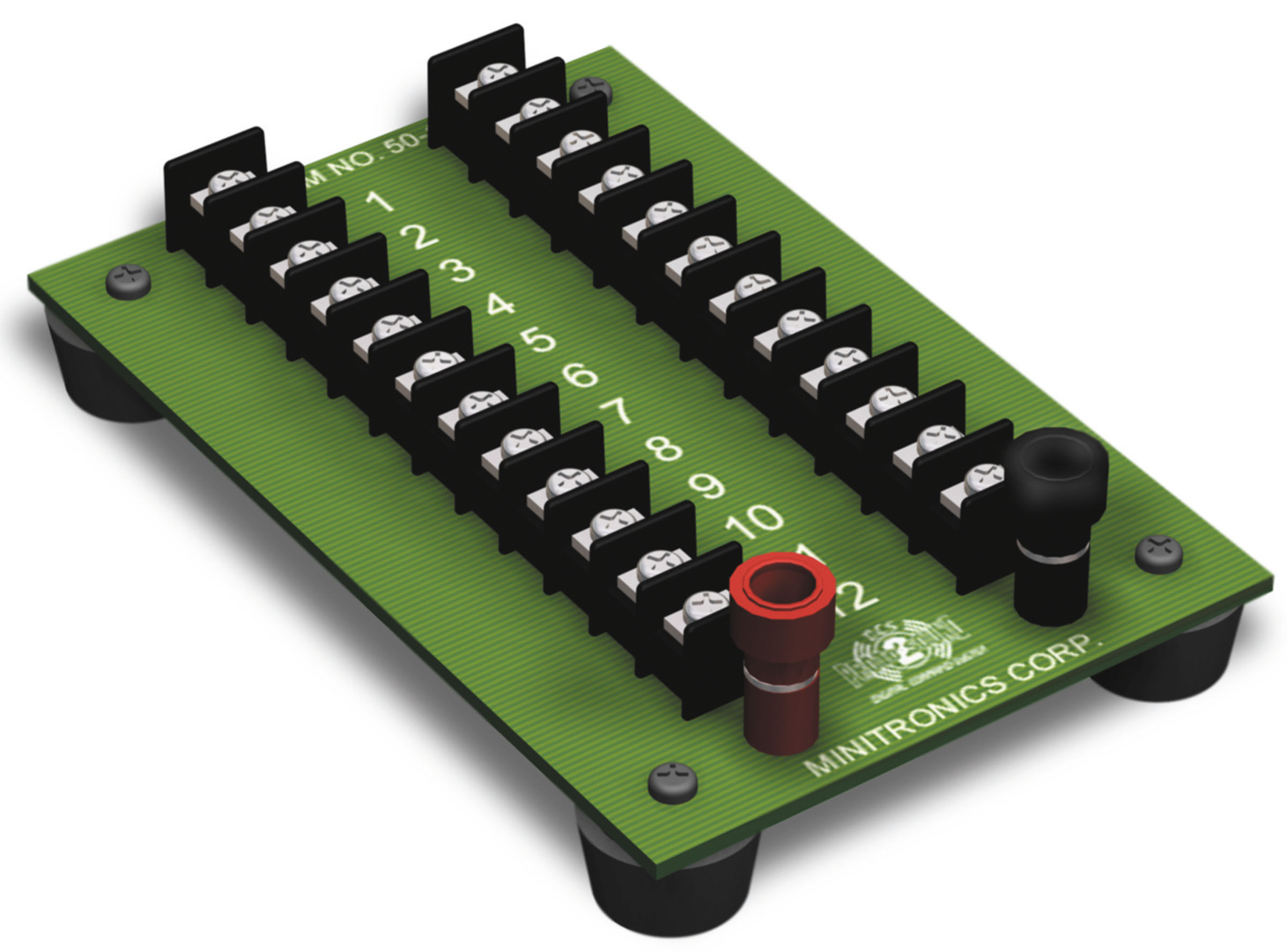
https://mthtrains.com/sites/default/files/product_images/50-1014.jpg

Taken from this topic https://ogrforum.com/...ack-how-do-you-do-it

allconnected_starwiring


"I wondering if someone can tell me if I might have a connection issue or the switch configuration does not allow power to the inner loop."

You didn't state what track system you are using. Most likely, you somehow have insulating or isolating rail sections as part of where you installed your switches.

If they are Fastrack switches- note the small pieces have a jumper wire that in your wiring diagram would need to be connected.

How to Cut the Power to a Lionel Fastrack Siding | O Gauge Railroading On Line Forum

Attachments

Images (3)
  • mceclip0
  • mceclip1
  • mceclip2
Last edited by Vernon Barry

I saw the last answer of using Realtrax switches. I do not know if you got used ones or brand new ones. Per the manual (example 072 switch)

https://mthtrains.com/sites/de...ction/40as16412i.pdf

Key here is the X spots indicating the track was modified removing a key brass contact

If you modified your switches or the track and/or they were used and the previous owner modified them- then they would not pass power.

Also note, especially if used switches, they can be damaged from Derailment shorts.

https://ogrforum.com/...h-problems-revisited

Thanks to @R. Hales for the below attached into from that topic

Attachments

Images (1)
  • mceclip0

I admit right now I’m not an electrician.

I have been reading with a degree of anticipation on what you find as your issue…

But I may add,

I can’t troubleshoot anything on my layout without a voltage meter.  

I don’t go under the layout without my meter and my new LED flashlight.

I can’t locate my trouble without knowing the last location that I have power.  

Whether it’s the transformer connection or it’s the power lead connections….

Just thought I would mention this…

Good luck

By the time the thermal breaker in the Z1000 brick trips you might have damaged or blown the fuse in the DCS explorer. The Z1000 has a 6A thermal breaker


Be advised that there is an issue with the response time of the thermal breaker of the Z1000.  It takes too long to trip.
I tested a 5A Airpax Sensata breaker with the Z1000 and it hummed and didn't trip right away either (if at all).  So those don't work with the Z1000 either.
What worked for me was an inline fuse holder and 4A Automotive Fast Blow Fuses.  Those blow right away.
Something about the Z1000 is kind of weird.   Airpax Sensata circuit breakers work with a ZW, KW and lots of other transformers.  Just not with the Z1000 and perhaps their other similar ones.
John
@ADCX Rob posted:

Because of the orientation of the non-derailing trigger rails, you don't have a ground/common connection to the inside loop. Connect a wire from each center common screw on each crossover pair to each other.

So finally I found a topic with some pictures of the bottom side of Realtrax 072 switches https://ogrforum.com/...ltrax-switch-problem

Yes, Realtrax intentionally leaves out the brass connection to the next piece of track on the curved and straight connections for the anti-derailing sensing rails.

So yes, that makes perfect sense why the inside loop is isolated when 2 of these switches are connected in a crossover.


Just sharing the below information as contrast or a reason I'm not a big fan of Realtrax.

Fastrack switches have built in sensing sections and even go as far as ensuring that the outer rail connection point to the next piece of track has a connection to both outer rails.

Example Fastrack switch with metal stamped connection plates that specifically connect the outer 2 rails at the point of connection to the next track section.

Attachments

Images (3)
  • mceclip0
  • mceclip1
  • mceclip2

So, from the manual, you need to connect the Common of both switches.

https://mthtrains.com/sites/de...ction/40as16412i.pdf

I would do it on both 3-4 and 1-2. Again, you are just connecting a common wire between the middle common connections between the 2 switches. This ensures your entire track plan has a common outside rail connection.

Attachments

Images (1)
  • mceclip0
@ADCX Rob posted:

Yes, or all 4 together if you want some redundancy.

Does this still allow the normal auto switching when an engine runs up to the conversion side of the switch Rob ?

It doesn't affect any switch operation.

As a matter of fact, you can use those terminals on the switch instead of lockons if you want to make a neat layout installation, these would be equivalent to lockon clip "2".  The screws closest to the switch motor("TrackACOutScrewTerminal") would be equivalent to the lockon clip "1".

https://ogrforum.com/...70#76748553645694870

Suggest reading that entire thread as there was a lot of discussion about different power supplies, voltages, when the fuse blows and so forth.

@MTH RD posted:

We would be very interested in knowing the exact circumstances under which you were able to blow the fuse.  The DCS Explorer has some pretty elegant (read expensive) current sensing hardware and firmware.  In out testing, we have not been able to blow fuses using the Z1000 power supply (18VAC ; 6A) and certainly not the DC supply included in the sets (16VDC ; 3.75A).

That fuse is only there to protect the Explorer from damage in the event of a firmware glitch or some extremely high current spike.  From a practical matter, blowing the fuse should be rare.

So, would you please tell me what power supply was plugged into the input of the Explorer?  Also, is there any chance that it was hooked to a track that had some other power supply connected?  Maybe even shared ground wires? 

Any insights are appreciated.  This is a new product and try as we might, we cannot cover all use cases in the field.  You guys can get very creative in breaking things.  ;-) 

By the way, using pliers, just yank the fuse out and stuff in a replacement.  The are tight but, they are supposed to be. 

One more thing.  Service has the fuses in stock just in case someone decides to run trains with an arc welder. 

@CyrilW posted:

Everything worded after connecting the switches. Thanks for all the help.

Had two trains running for a couple minutes, then lost power. Looks looks like the fuse blew on the DCS Explorer. Hope it's not fried. @Craftech Where did you install the inline fuse holder?

I run Conventional,  I put an Inline 5 amp Blade fuse holder on both my MTH Z-1000 Transformers on the positive red banana jack for Track power, works great, they blow quickly on a derailment, a TVS Diode across from the Red Hot and Black Common Track Connections on the Z-1000's outputs, and mounted an 1/2 inch wide round Amber 12 Volt Automotive LED Marker Light connected to my Buss Connectors from underneath the layout to next to each Transformer to show I have power going to the track. I also have TVS Diodes at each track connection, when I finally finish all the trackwork, 2 independent loops, I plan to put TVS Diodes inside each of my locomotives. I don't have any of the equipment for command control, but I would put inline fast blow fuses like the blade fuses on any power inputs to protect your electronic units from damage.

@CyrilW posted:

Everything worded after connecting the switches. Thanks for all the help.

Had two trains running for a couple minutes, then lost power. Looks looks like the fuse blew on the DCS Explorer. Hope it's not fried. @Craftech Where did you install the inline fuse holder?

Right at the Z-1000 inline with the hot side.

Z-1000 Hot to one side of fuse holder wire (direct or with a lead wire first).  Other side of fuse holder  to wherever you have joined your Hot wires that go to the center rails.


I have a bunch of extra inline fuse holders if you need one.  Contact me if you do, I'll send it to you.

In terms of all the TVS diode suggestions here, GRJ posted maybe a week ago that too many TVS diodes can interfere with a DCS signal.  Maybe he can elaborate.  I just remember him posting it.

John

@stan2004 posted:

How did you get clearance on the "switch block" since presumably it would need to go between the tracks?

IMG_9013

Hi Stan. I do not have clearance for the switch blocks. I had to omit them. I am able to lift the track and plug them back in when I want to change the position of the switch. Not sure why MTH didn't make a smaller block that would fit in this configuration.

CyrilW,

Easy solution.  As Vernon Barry said, add a distribution block, then add two(2) lockon connection to both the inner and outer tracks.  Your Z1000 should be able to handle this setup and apply the power to the inner loop.  And reference your crossover switches, it appears you are using O72 switches and those switch block positions are a pain!  Two ways to solve this:  add a 3.5 in. track between the switches.  This will give you the space between tracks you need to keep the switch blocks on the inside of the track.  This does increase the track width on the front section of your layout.  The other is to trim a notch into the plastic roadbed to fit the switch block.  I tried this and it works pretty good.  My engines come close, but do not touch.  I run approx. 100 feet of Realtrax track and 23 switches, all with one Z4000 for the last ten years with little problems.  When I do have a problem, it usually is operator error.  Hope this helps.

Add Reply

Post
×
×
×
×
Link copied to your clipboard.
×
×