On a prewar 072 switch, the rails that activate the non-derailing feature are insulated and closer to the switch. This design was not used later. This picture shows the non-derailing pickup on a prewar 711.

There is a problem with this non-derailer design. The engine and cars center pickups cross the ACTIVE non-derailing contact rail. This can trigger the switch when not desired causing a de-railment. When going straight the center pickup momentarily contact the turn non-derailing rail. When turning the center pickup momentarily contacts the straight non-derailing rail.
If there is only one pickup on a car, it may act like a ground and throw the switch the other way with a car or engine on the track. The same will happen when one of the 2 pickups on an engine does not make good contact.
When using a postwar switch motor and the power tap for constant voltage, running the engine slow in conventional mode will have a large voltage difference and it may throw the switch causing a de-rail.
I have seen this derailing with these switches in use. It doesn't always happen with engines, but one out of 50 times is too much.
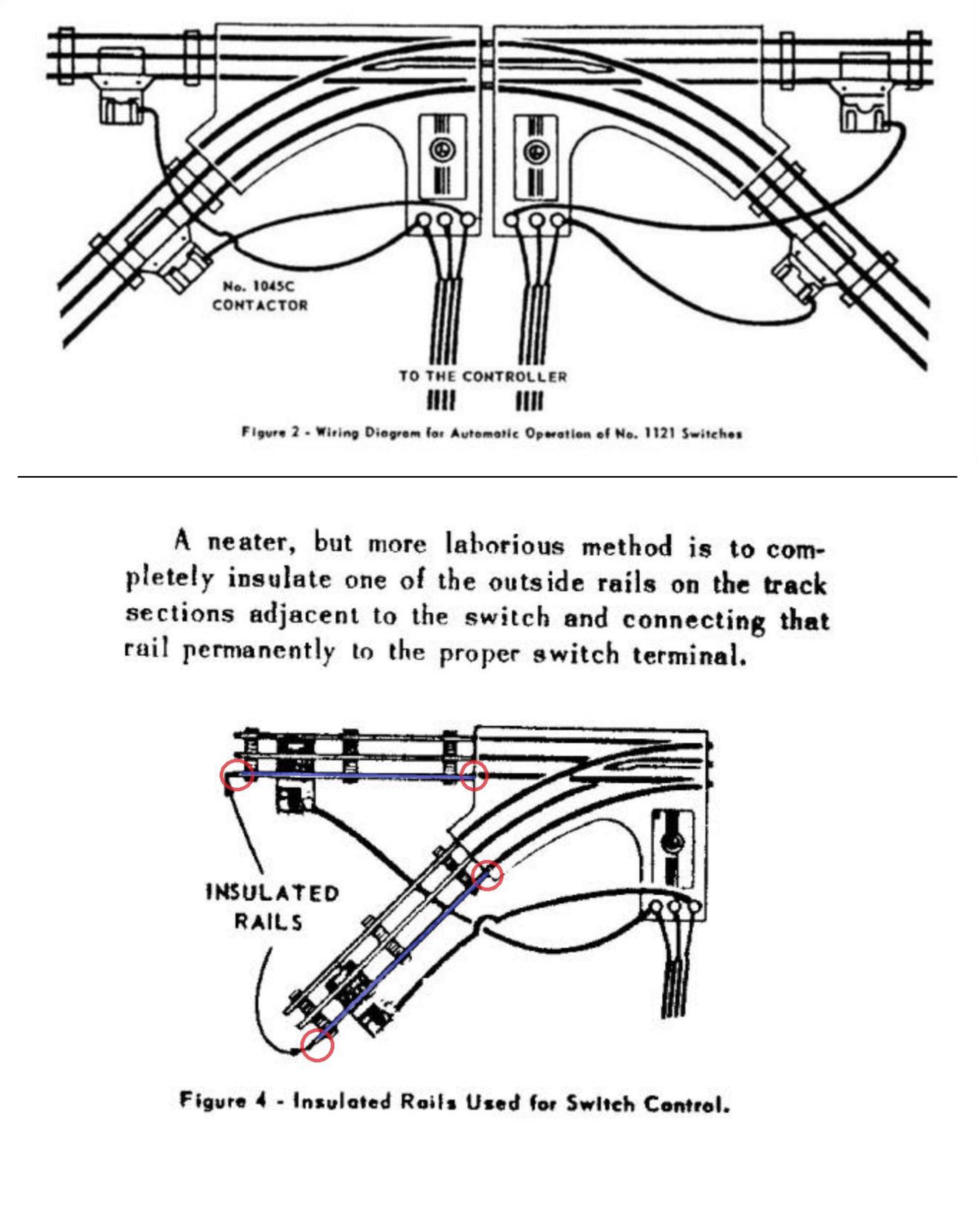
What I suggest is to disconnect the wires from these non-derailing pickups and leave the rails insulated and inert similar to postwar switches. Then the 2 tracks after the switch have an outer, insulated rail. The insulated rails will need insulation pins on both ends to function correctly. Then a wire from the insulated track to to the corresponding left or right post on the switch motor. You now have a more up to date non-derailing contact. The center pickup never touches the non-derailing rail to cause problems.
Simple schematic of adding 2 tracks with insulated rails for non-derailing.

If it works bacwards, just switch the wires on the switch.


