Replies sorted oldest to newest

Paul

Flash did a great job in explaining the primary function of a relay.  Another way at looking at a relay from a very high level is that a relay is nothing more than a switch turning on another switch.  When applying power to the relay you are turning on a switch that then moves the contacts of an internal switch to either an on or off position.

A relay can also switch multiple circuits at once and perform simple logic functions. 


here is a post on using relays for block detection


http://www.jcstudiosinc.com/Bl...=410&categoryId=


here are relays switching loads in a control panel


http://www.jcstudiosinc.com/Bl...=635&categoryId=


here are relays,used with modular timers


http://www.jcstudiosinc.com/Bl...=481&categoryId=


Dale H


Originally Posted by Harleylito:

I've read many threads on the forum about using a relay for accessory operation etc.  Could someone explain to me what a relay's function is and how it helps the operation of switches/accessories?

Please remember "I am a simple man" and need things explained in "simple terms".

Paul

Maybe one or more of these websites will help in trying to understand what relays are and how they operate.

http://electronics.howstuffworks.com/relay1.htm

http://www.howstuffworks.com/relay.htm

http://www.autoshop101.com/forms/hweb2.pdf

http://www.1728.org/project3.htm

http://www.youtube.com/watch?v=zY7XXSG6nbo

http://www.youtube.com/watch?v=RjYyAPcr_7k


relay

Attachments

Images (1)
  • relay

Ralph - I'm a visual learner so these links have helped me understand the relay operation.  I guess the only question I have is "why use them".  I understand that the relay uses a small amount of power to turn on an accessory that may use more power.  But once on, doesn't the accessory still need that extra power to remain on?  So why not just run a hot and common directly to the accessory with a toggle switch?

These were very informative and I'll look at them several times until things start to sink in - thanx for your help

Paul

Originally Posted by Harleylito:

Ralph - I'm a visual learner so these links have helped me understand the relay operation.  I guess the only question I have is "why use them".  I understand that the relay uses a small amount of power to turn on an accessory that may use more power.  But once on, doesn't the accessory still need that extra power to remain on?  So why not just run a hot and common directly to the accessory with a toggle switch?

These were very informative and I'll look at them several times until things start to sink in - thanx for your help

Paul

Paul,


There are several reasons for using relays in model-railroad circuits. Among them are the following:

  1. Sometimes we want to use metallic-wheel contact on an insulated running rail to turn on or to turn off a trackside accessory (e.g. gateman, signal, semaphore, crossing gates, etc.) without having to depend on solid, reliable, low-ohmage contact established by the wheels.  And we don't want sparking at the track contact.

    A relay's coil requires much less current than do the accessories. So if we let the track-contact turn on a relay (especially if the relay has a capacitor in parallel with its coil), we get a smooth, non-sparking, reliably "holding" turn-on and/or turn-off action — when the relay is activated, its magnetically activated switch contacts turn the desired accessories on or off, and the relay's contacts can easily switch large currents.


  1. Sometimes we want to turn on and turn off more than one device at the same time -- maybe, for example turn off one set of lights, turn on another, turn on a siren, etc. And maybe these various devices run at different voltages (e.g. 16 VAC, 12 VDC, 5VDC, ...). Also maybe these devices are located at some distance from where the controlling contact, pushbutton, or toggle switch may be mounted.  In such a case, it is much simpler to run a single wire (or two) from the controlling switch to a remote relay that is located where the devices are, and then do the more complex wiring at the remote site with the relay acting as the multiple-switch.

There are probably other uses, but these are what pops up to the top of my head right now.


One of the things that relays allow is trackside control of signals and operating gates. Triggered by a common outside rail wheel roll-over, a lift gate can be powered up and down.
Note this MTH gate has (5) lead wires.  Black and Red are power to the gate. They are attached to the center and outside rail for simple 12 volt AC power in this picture. There are three control leads, White, Blue and Yellow .
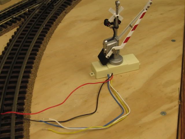
Blue and yellow wires held together with my thumb and finger, the gate goes down and stays down.
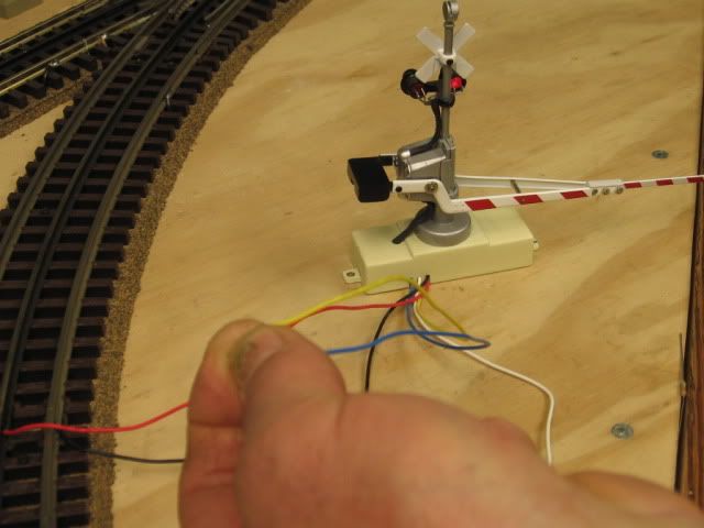


Blue and white together and the gate goes up and stays up.  Application is a relay. NC, Normally Closed),  C, (Common, usually a center terminal), NO, (Normally open). The automated trigger circuit would be via an isolated outside rail section leading to the crossing.
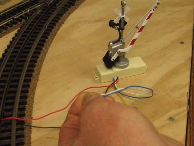
Relay board. (Relay is the black box at the bottom of this board).

Brown and Red are power to the board.

Green is an isolated(insulated) rail input to the board, (the trigger circuit).

Blue (C), Yellow(NO) and White (NC) are the relay points.

 This setup required (6) conductors  between the lift gate and the relay board.

Last edited by Mike CT
Originally Posted by Harleylito:

Ralph - your explanations makes things much clearer - I really appreciate the time you took to clarify things for me.  I'm in the process of breaking down my layout and redoing it this winter so I would like to incorporate them into my accessory operation.  

Thanx again for your insight and help

Paul

A few more words about relays:

A) Relays are available in many configurations of the switching contacts. The first image attachment below shows some of these configurations.

A.1) The simplest configuration is the SPST (single-pole single-throw): there is one contact "pole" which is electromagnetically switched from one position to the other.

A.1.a) If this contact is of the NO (normally-open) type, then when the relay is "off", the pole makes no contact at all. But when the relay is powered "on", the switching pole does make contact (and turns on some accessory device.)

A.1.b) On the other hand,if this contact is of the NC (normally-closed) type, then when the relay is "off", the pole is making contact and turning on some accessory device.  But when the relay is powered "on", the switching pole no longer makes contact (and hence turns off the accessory device).

A.2) SPDT (single-pole double-throw) relays have a switching pole that changes its position between two different contacts.  When the relay is "off", the switching pole makes one of the contacts, and when the relay is "on", the switching pole makes the other contact.  Thus it could be used to turn off one device (e.g. green light) and simultaneously turn on another device (e.g. red light).

A.3) And relays are available with multiple (electrically distinct) switching contacts that all move together when the relay is powered "on":  DPST-NO, DPST-NC, DPDT, ... 4PDT  (where DP means "double pole" and 4P means "4 poles).  These more complex switching configurations offers many different possibilities for electrical control.

B) The coils of different kinds of relays are designed to be powered by different electrical voltages -- some are AC-powered, and some are DC-powered.  For model-railroad purposes, the least expensive and quietest ones are the low-voltage DC-powered (5 VDC, 12 VDC) relays.  To power these from model-railroad AC transformers, the coil's circuit would require a diode (to block one half of the AC and change it into half-wave DC), an electrolytic capacitor (to smooth out the ripples in the half-wave DC and to store up enough initial charge to give the relay a "kick-start", and possibly a resistor to provide a voltage-drop so as not to exceed the coil's specified operating voltage.  The second image attachment below shows an example of this.

RelayContacts

circuit

Attachments

Images (2)
  • RelayContacts
  • circuit
Originally Posted by Mike CT:

One of the things that relays allow is trackside control of signals and operating gates. Triggered by a common outside rail wheel roll-over, a lift gate can be powered up and down.
Note this MTH gate has (5) lead wires.  Black and Red are power to the gate. They are attached to the center and outside rail for simple 12 volt AC power in this picture. There are three control leads, White, Blue and Yellow .
Blue and yellow wires held together with my thumb and finger, the gate goes down and stays down.


Blue and white together and the gate goes up and stays up.  Application is a relay. NC, Normally Closed),  C, (Common, usually a center terminal), NO, (Normally open). The automated trigger circuit would be via an isolated outside rail section leading to the crossing.

Relay board. (Relay is the black box at the bottom of this board).

Brown and Red are power to the board.

Green is an isolated(insulated) rail input to the board, (the trigger circuit).

Blue (C), Yellow(NO) and White (NC) are the relay points.

 This setup required (6) conductors  between the lift gate and the relay board.

can someone give me a direct wiring diagram and how to on wiring a Gold lionel Gateman accessory i am afraid to hook it up due to the fact that I somehow wired it so that constant current went through the coil of my wifes Nutcracker Gateman and I do not wan to make the same mistake twice.

With this said I would also like to figure out the easiest way to trigger this gateman to stay out till the train has passed and then go in automatically on the first go round I used a DC Transformer and an MTH Scale Trax ITAD.  Which when i first hooked it up it ran fine and worked marvelously but when i took it out to put it on the Christmas Display it would not work and after disassembiing it i found that there were brown spots on the Coil Which according to repair technicians I fried the coil But i really do not know how i did it

 I need simple terms and this wire goes here and that wire goes there as well as a picture Also if I am to use something diffrent than what I have I need a shopping list from Radio Shack or Electronic Parts Supplier  to get what I need besides simple wire


Another way to look at a relay is as an amplifier. A small signal applied to the coil can control a very large signal via the relay's contacts. Relays can handle much more than AC or DC currents, such as radio frequency signals as well. Also, latching relays offer an unusual but very clever twist on normal relay operation, useful in many applications. The old standard electromechanical E-unit was a form of latching relay.

Post
×
×
×
×
Link copied to your clipboard.
×
×