This reply is to everyone interested, but it's more directed to 1drummer and TedW.

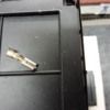
I have enclosed 3 photos at drummer's request that show how fastrack is connected.  TEDW enclosed a photo when he responded that shows a much better picture of fastrack and where the connection points are located under the track.  So if you aren't familiar with fastrack, you have to connect to the hot and ground points underneath the track pieces, straights and curves.  To add to the nightmare, only Lionel's specially made Terminal Track piece that has its own item number and is very different from other straight pieces in that the groove you need along the side of the track for the wires to protrude out from under the track is installed at the factory and the wires you need, which I think are 22 gauge, I may be wrong, are also installed at the factory and then you connect your wires to those wires.  I hope the drenching smell of sarcasm isn't lost on anyone who read that.

Photo 1 is a bad attempt at showing you what the connection clips look like.  Again, thin, narrow sheet metal designed to take a wire connector that looks like photo 3, the clearest of my photos.  TEDW sent a better picture of the underside but you can't see the silver sheet metal clips.  But you can see how narrow the area is.  TEDW, I too use those connectors, but from my photos you can see that I use the one's that do not have the plastic collars on them.  My attempt with those photos was to show how narrow an area you have to put wire in them, and how shallow the clips are.  Photo 2 shows, I hope, how close together both sets of clips are sitting.

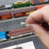
I failed to mention in my first Gettysburg address, (sarcasm as to how long it was to read), my layout is on the floor.  It's not on a table, or elevated in such a way that you can drop the wires into a hiding place, let them dangle, and have ample room to connect.  The wires I ran had to be run out from under the track piece, along the side of the track, and finally through the bottom of the cabinet to the terminal board.  Look closely between the cracker jack car under my hand, and the rice krispies car in front of it, that black spot is wide hook Velcro using the porch carpet as its loop side and holding down the wires.

So as you can hopefully determine from all this information, 14 gauge wire compared to 18, would be a bit more bulky in this case.....or maybe it wouldn't.  But I was looking for ease of run along a floor so this is the best I could come up with at the time.  Go thin, but don't go wrong.  And to date it appears to work without complication.

Attachments

Images (3)
  • track connection points: sorry so blurry, cell phone, too close
  • track wire connector 2: blurry but you get the picture
  • track wire connector: finally, a clear look

I’m an MTH/ Gargraves track guy. 

The lockons for MTH are simple. 

You can add them on any track section with out having to dismantle the track.

From the pictures, it seems you need to commit to every section, “just in case”. To avoid the need for track dismantling. 

Since I run in power blocks, I would commit to a connection point every 10-15’. 

And use the female blade terminal like Tedw is doing. 

Because the track to track connections on Lionel look sufficient, mechanically speaking. 

Not much else will make that system easier to utilize. 

Thanks for the information.  I do wish I had known about MTH before I got started.  I only knew Lionel.  So when I went looking for cars and locomotives and track, I shot right straight to the Lionel website.  I saw fastrack, decided, that's me, and bought a box of 50 straights and some curves.  Then I discovered MTH, and Realtrax, and as you said the lock ons, and by that time it was too late because I'm retired, Warren Buffet is not my uncle, and I don't play the lottery.  So I had to proceed with what I started.  It took me forever to get my room ready for track, so by the time I got around to track, wire, TIU and AIU and transformers and the Base 1L blue box, I was as lost as a pair of glasses that were never in the house to begin with.

So if I do anything at all, it will first be to remove all the screws I used to secure it to the floor.  How I ran the wire is fine, it gives the look character.  What I would do is concentrate on running the 14 from the TIU to the Terminal Board, probably buy a 24 screw board so I can eliminate the doubling up, and run each booster wire individually one at a time, black and red wires so as not to get myself into some sort of bird nest of confusion because I went too fast.  I can use shrink tubing to secure the wire to the clip, I have plenty of extra clips.  The biggest obstacle is deciding whether or not to go about it.

As I have stated, it may not be right, but since it works without noticeable problems, or for that matter, any problems, why fix what isn't broken.  It's like the deadbolt I installed on mom's sunroom door.  I installed it upside down.  Woops.  But it works.  It latches, it locks, and it's upside down.


JOHN H

I did something similar in that I kept the 16 gauge from the TIU to my 12 screw terminal block, which caused me to have to double up on a few to make 17 drops.  I stayed with 16 at the screws, but used the 18 gauge to run from the track pieces to the pigtails under the screws and wire nutted them together.  I could easily, well that's relevant I guess, run 14 from the TIU to the terminal screws.  Not sure how much that would get me if anything but guess it's worth a try.  You mentioned 10's?  for track signal, not following.  But as for 18 volts, well, my TIU is supposed to be generating 18 volts through the fixed out 1 port through the wires to the board and out to the track pieces, so I guess I have 18 on all tracks because all of my tracks are connected as one via switch tracks placed strategically throughout.  Here's a question.

Just asking.  Not trying to show my obvious lack of knowledge.  If I run a second TIU from the wall plug at the back of the room and hook that one with drops to track pieces at the back of the room, would that help generate more efficient power to the track?  My shade tree electrician theory is that if I have 18 good volts coming from both directions, they would meet in the middle and the long runs would become in a sense, short runs.  Am I making any sense or have I gone completely off the 'rails'?

John H posted:

. A short drop of smaller wire does not make a significant impact, in my opinion. 

Well, Electrical Theory and Science prove your opinion wrong. 

Impedance Mismatch is a problem. 

Wire has inherent resistance-and if you are pushing 10 Amps, you are in danger of power transfer failure. 

Simply put, the greater heat from higher current can damage the smaller wire. 

Plus, the smaller the wire, the less conductivity-which is due to higher resistance. 

If you can maintain the same wire size, especially when powering your Trains, you are better off. 

Remember, those wires also carry the signal for the control of the train. Damaged wires+loss of control=broken Engine. 

Im not clear on the size mismatch of your specific installation, and you may not be in any real immediate danger. So consider this a FYI for those who are about to build a Railroad-use the same gauge of wire for powering your trains. 🚂

Yardmaster96 posted:

JOHN H

Just asking.  Not trying to show my obvious lack of knowledge.  If I run a second TIU from the wall plug at the back of the room and hook that one with drops to track pieces at the back of the room, would that help generate more efficient power to the track?  My shade tree electrician theory is that if I have 18 good volts coming from both directions, they would meet in the middle and the long runs would become in a sense, short runs.  Am I making any sense or have I gone completely off the 'rails'?

First-your TIU is not generating any Current or Power-it’s only passing the Current/Power from your Power Supply-and adding the DCS signal onto the conductor. 

As far as adding another TIU

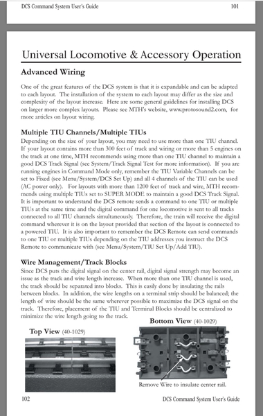
Do you have more than 300’ on one Fixed output with more than 5 Engines?

6C694BB4-B4E4-49BB-8EBB-A5407F55C522

Attachments

Images (1)
  • 6C694BB4-B4E4-49BB-8EBB-A5407F55C522

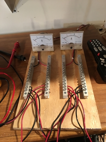
I have divided my trackage into equal blocks. 

As you can see from my power terminals I have 6 track blocks-3 on each fixed output of the TIU. 

I do have over 300’ of track. 

And I have 17 engines-which are all usually on the rails. 

Here’s a tour for those who haven’t seen it

https://youtu.be/wtE8Ma3CV0Y

And Im adding another yard, off of a Y along the walls to the left of the duckunder. 

Because I’m breaking my own OSHA Rule. Which is the percentage of Trains to Track must be below X% -else you just end up becoming a Train Displayer and not a Model Railroader. (no room to run trains)😁

To answer one question, if it were directed at me, not sure, I have a 20x20 room in which the majority of the floor is taken up by the layout.  I have 5 locomotives attached to what has become 5 trains.  I can only run 3 of the 5 at a time.  The only issues I've seen with this layout are a problem that one engine has responding to 1 or 2 SMPH.  Say i'm backing it up to hook to another set of cars, or even its set of cars, when I get down to 2 or ask it to back up at 1, it jerks a bit.  But once I reach 3 it smoothly moves backward or forward.  Only one of them does that.  But to say I've experienced anymore problems with spontaneous starting or engine out of range or spontaneous runaway speeds, that stuff stopped when I ran the booster drops.

Drummer you mentioned not getting "warm".  I was going to ask that when I got home from town, and I'm home from town.  I found an all metal grounding buss at Lowes.  Then it hit me, if I generate power to that metal rod, it will become an electrified metal rod.  Good for my power output, bad for my body.  How did you solve the electrocution problems?

Oh and to the person who emphatically stated, "NEVER!" use two TIU units on one track.  Thanks.  Appreciate the information and I understand completely.  Had to ask, got my answer, now I know. 

This is why we field questions like that on the forum.  It's not to look stupid, it's to get someone who knows to tell you that's wrong so you won't do something stupid or that it is correct so you can do something right.

Yardmaster96 

there is no electrocution concern from just one bus bar-you need to get across both to get shocked. 

And the 10 Amps is not a concern for dangerous shock unless you’re standing in water😁 or otherwise sufficiently extensively grounded. 


The heat issue of the bus bar will only occur if you have a loose wire connection on the bar, or a long term “short” across the rails-which will/should trip your breaker. 

Yardmaster96 posted:

To answer one question, if it were directed at me, not sure, I have a 20x20 room in which the majority of the floor is taken up by the layout.  I have 5 locomotives attached to what has become 5 trains.  I can only run 3 of the 5 at a time.  The only issues I've seen with this layout are a problem that one engine has responding to 1 or 2 SMPH.  Say i'm backing it up to hook to another set of cars, or even its set of cars, when I get down to 2 or ask it to back up at 1, it jerks a bit.  But once I reach 3 it smoothly moves backward or forward.  Only one of them does that.  But to say I've experienced anymore problems with spontaneous starting or engine out of range or spontaneous runaway speeds, that stuff stopped when I ran the booster drops.

Drummer you mentioned not getting "warm".  I was going to ask that when I got home from town, and I'm home from town.  I found an all metal grounding buss at Lowes.  Then it hit me, if I generate power to that metal rod, it will become an electrified metal rod.  Good for my power output, bad for my body.  How did you solve the electrocution problems?

Oh and to the person who emphatically stated, "NEVER!" use two TIU units on one track.  Thanks.  Appreciate the information and I understand completely.  Had to ask, got my answer, now I know. 

This is why we field questions like that on the forum.  It's not to look stupid, it's to get someone who knows to tell you that's wrong so you won't do something stupid or that it is correct so you can do something right.

FWIW, it has been mentioned on the Forum in a number of threads in the past that, "MTH has at various times advertised that DCS engines run smooth at 2, 3 or 5 SMPH ……. newer PS3's should be the best at slow speeds", so it is very possible that there is no "correctable" problem at crawl speeds.

Smoothness at slow speeds also depends on age of an engine.  I have 2 1992 or so Weaver diesels, upgraded to PS2, that will crawl at 1SMPH.  They are, let us say, well broken in.

FWIW, my layout is wired very oddly, because it was built long before DCS, for conventional operations, with some 70+/- toggle-switched blocks, each switch on a central control panel.  These are fed from 6 transformer channels, now through 2 TIUs, one using all 4 channels and the other only the variables.  The two fixed are fed from a Z4000 with the Z4k receiver.  Two variables are fed by a PW ZW, and 2 by a PH180.

Common is a 12-gauge looped buss, with feeds wherever needed to tracks & accessories.  By looped, I mean that when the buss leaves the U-posts, it goes in two directions, meeting at the far end of the layout.

Hot feed goes from a TIU output to the control panel, where it feeds all of the toggle switches for blocks on that channel.  From each toggle switch, 14-gauge goes to the particular block.

I do not run the common/ground throught the TIUs, but all black TIU outputs are connected to the common buss; nothing on TIU black inputs.  This is to avoid overloading any TIU internal circuits; I do not have the time to go into a long discussion of why I do this.

Violates all the "laws" that have been dreamed up for wiring DCS, but bottom line:  10s everywhere, and conventional can also be run.  Often I have 6 DCS trains running on intersecting routes, including 3 on one 0.9 scale mile loop.but that keeps me on my toes.  Also occasionally run conventional and DCS at same time on same track, but that's more work than fun.


drummer- In regards to the light at the end of the track.  I've had others tell me the same thing.  One problem.  I'm not familiar with all the tricks of the trade.  I told the forum a few months back, and I wasn't joking when I said this.

When you give me information on how to fix or repair or work around something, please keep in mind, where railroading and electronics are concerned, I'm not stupid, but I'm also not Einstein.  No where in my name or lineage does the name Nickola Tesla show up.

I greatly appreciate all of the help you are giving me and I hope to be able to put it to good use, but in regards to the light...….How?  I use Fastrack.  You've seen how it allows people to attach wires to it.  What kind of light are we talking about.  Is it a big light like the ones in the lighted caboose, is it a small light like the ones on the switch tracks that tell you red or green for open or closed.  Is it a metaphor for something else I'm not familiar?  Just need a bit more information. 

Thanks 

Don't hold me to this......or do and I'll just deny it and attack you with fake news tweets.  But I think the Rev L is the new TIU for the WIFI driven DCS that works on your cell phone or tablet and let's you run your trains until you get a phone call or text and have to scramble to get back to the train management screen ignoring the phone call from your kids, whom you forgot to pick up school....not to mention it's raining.

I did the signal test with the affected engine, my Union Pacific ES44AC circa 2017, with PS3, ESP, SPCA and AOK, and the reading was a perfect 10.  I ran it at 1.  It lunged forward, stopped, lunged again, stopped, looked like a UPS truck with a bad transmission.  I changed direction, at 1, and it proceeded to lunge backward, at 1SMPH, but kept the 10 signal both ways.  My CSX Railking class engine did fine at 1.  My ES44's are both Premier class.  I didn't test the two SD's. 

This engine, as well as it's adopted brothers on the other four tracks all sit at the very rear of the third, inner most oval where their parking tracks attach to the inner most oval via a switch track.  So it appears on paper that my 18 gauge wire is allowing a full signal, at least that far back.  I tested the signal back at the first of this year, I believe it read 10 on the outer most track as well at the same area of that oval.

I've forgotten how to do a voltage test with an engine.  I did one, again at the first of the year, and it read 17 or 18 pretty much the entire way around the track.  So for now, I think I'm going to go the route of "it doesn't appear broke, so I will refrain from fixing it."

Thanks for all the information and your help, and if anyone else has a comment or idea or would like to chime in on this, I'd be glad to talk to you. 

The Rev L has been around for about 5 years.  Any TIU, regardless of vintage (even the original issue) works with the Wifi app.

If you loco does that at 1SMPH, check to make sure wheels, rollers, and track are clean.  New track sometimes has a film, and rollers gather glop.

The only way to do an accurate track voltage test is with an AC voltmeter clipped directly to the track.  The loco test is done via a softkey.

Good to know and to add to the helpfulness of the information.  Instead of looking on the bottom of the TIU, just look to see if it has a USB port.  Mine does not.  Serial port and telephone jacks. 

I watched a video from the National Model Railroad Academy (Birthday gift).  Caters to the HO hobby, but the part about wiring the track is universal.  The guy who made the vids is known as a Master Modeler.  So I am telling you what he said.

He uses 12 gauge wire as his Bus wires leading from his DCC out to the track connections.  At the track he keeps his feeder wires short, and uses, unless I got this wrong, 18 gauge wire.  Or maybe he said you can use 16 or 18 if you want.  I have to use 18.  It's just easier to make the track connection.  But, this winter, I am going to wire the track with 12 gauge from the TIU to the terminal block and out to the connection points where I will connect 12 to 18 using a short pigtail run.  I plan to use a combination shrink tube/heat solder butt connector, then go overboard and use regular shrink tube over top of that to ensure a strong connection on both sides.

Thoughts?

1drummer posted:

Yardmaster96

the shrink tube is cosmetic 

it doesn’t really aid in the electrical property

You're right drummer.  I was merely doing that part as cosmetic even though it would be hidden under a piece of Velcro.  You just saved me some money because I didn't have that size on hand.  Thanks.

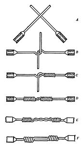
Excuse me for stepping into this. If you're splicing two sections of wire, my preference is a Western Union splice. Great for solid core. Not so good with stranded. Overkill? Solder after you splice. As for shrink wrap, it provides electrical insulation. It isn't merely cosmetic. Two other options: Liquid Electrical Tape or good old #33 3M Tape.

Western_Union_splice


Attachments

Images (1)
  • Western_Union_splice

Add Reply

Post
×
×
×
×
Link copied to your clipboard.
×
×