Thank you for the help.
|


|
Replies sorted oldest to newest
Looks like the steam exhaust line from the Dynamo, which would be piped rearward and exit behind the stack, pointing vertically.
Hotwater, I understand a dynamotor is generally defined as a rotary electrical converter (motor-generator). Did you mean turbo-generator or dynamo, which produces electrical power with a steam turbine? Just wondering about the terminology.
Hotwater, I understand a dynamotor is generally defined as a rotary electrical converter (motor-generator). Did you mean turbo-generator or dynamo, which produces electrical power with a steam turbine? Just wondering about the terminology.
Right, I meant Dynamo. I'll go back and edit that. Thanks.
Yes, I agree that it does look smaller than the bracket it is sitting on, in your photo. Not to mention, it does not have the exhaust piped to behind the stack either.
It would appear that most steam powered appliances on the M1a/b have a supply pipe and an exhaust pipe. Control of appliance most likely is done with air or mechanical valves, so there would be a third pipe usually a smaller gauge copper pipe for the air control on some appliance. Air pumps, stoker feeder motors, water injection, electrical power (as mentioned), most all steam powered, air control, if required. Most of the exhaust from these motors, etc. appear to pipe to the smoke box, may be a safety feature ??? Steam (exhaust), invisible, easily burns???, so you wouldn't want exhaust jets of steam at several different location on the locomotive.
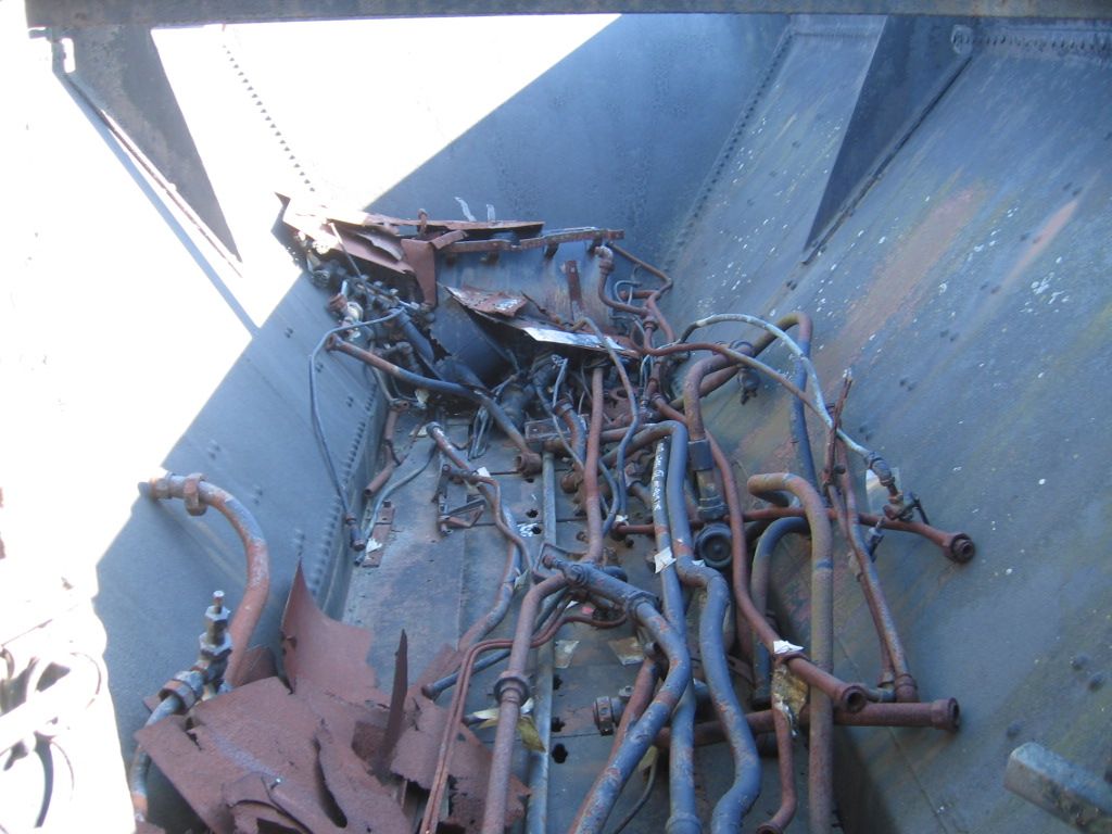
Unfortunately the M1a/b at the Railroad Museum of PA is a static display. A lot of the piping looks like this, in the tender.

I followed the steam (exhaust) piping off the two Air pumps. It appears to manifold with other pipes in to the lower smoke box area front of the locomotive. I could be wrong and often.

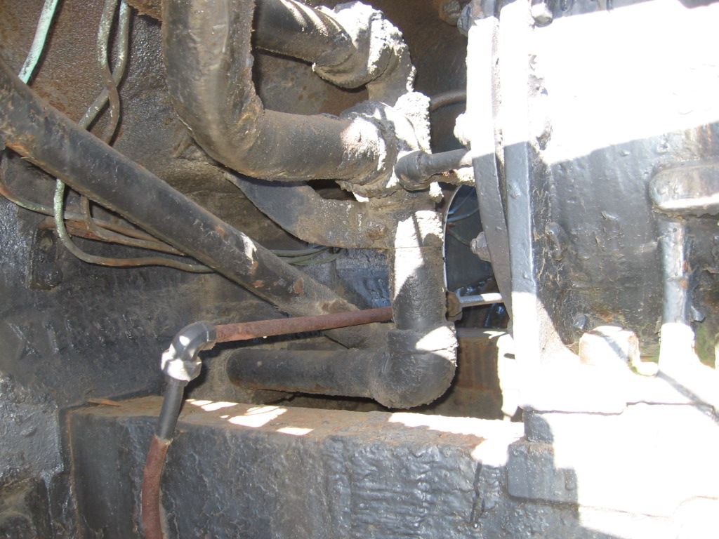
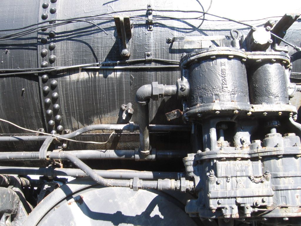
I looked for detailed pictures of the steam generator (dynamo) but couldn't find them. Here is my M1a/b picture file.
When I was bashing together my SAL Class Q3 Mikado, I thought I was looking at a maze when trying to figure out what all the pipes were for and where they went.
Here's a photo of engine 355, look at the pipe going up behind the smokestack:
2nd best bet is too find as many photos as you can of the real deal and go from there...1st best bet is to ask Jack (aka Hot Water).
Now that I think about it, I believe it was determined that pipe comes from the booster engine on the trailing truck.
These two air pumps are steam powered and have a steam exhaust. My guess is that a couple of the pipes down off the mounting rack are steam exhaust to the bottom of the smoke box. Other pipes would be air to storage tanks. Usually part of the assembly pictured is a small filtered air intake to the pumps. Air filters may have been oil bath type filters were air is suck through an oil bath to remove dirt. They appear small on the M1a/b. Pumps were positioned on the front of the locomotive to inhibit smoke in the compressed air.

Mike,
below the smokebox front is the one area I never got a good feel for, about all I can see in that photo is what looks like a pail of some sort sitting there. I couldn't lighten the photo enough to get a good image.
Sure is a lot of "stuff" on that frontend.
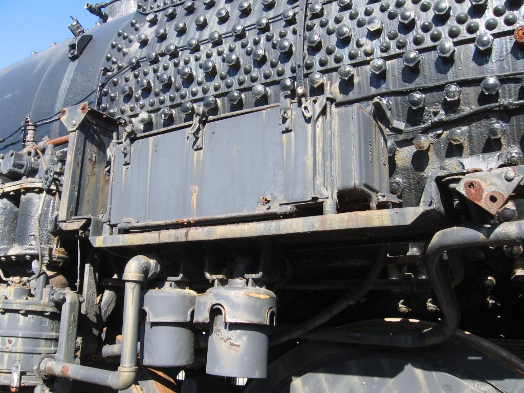
These two cans, low in the picture, are probably the compressed air filter intakes on the M1a/b

The M1a/b air pump(s). Note that the two can assembly top is the steam drive, bottom assembly is the air pump. Note the smaller pipe, low in the picture with the 45 degree offset, is air to the forward tanks. Above the air pipe, from the center of the larger cylinder, is the steam exhaust to the lower smoke box. Note the "T" in the line that connects the second pump not shown in this picture. As this forum goes, I'm sure if I'm wrong someone will correct me.

Before you guys get too far along with pipes, cored unions, flanges with bolt heads, etc., consider Proto-48. That is what they do.
I make my own steam. I will use a high quality lost-wax appurtenance if one is laying around, but I have been known to use sand-cast air pumps and lathe-turned dynamos. I hope never to get sucked in to the idea that my locomotives need every single detail the prototype had.
What Bob 2 said! Take it from me and Bob2 it begins to get really tedious and when you're finished,one cannot really take in everything.
That is why diesels are so much easier to detail than steam, IMHO.
Just to confuse things further, here's a mess of explaining on this forum from 2013:
Thanks to all who have shared. For me, I just wanted to add a few details. There are some details that I don't mind that are left out and others I want to include. The nice thing about this hobby is that there is room for everyone. Someone said to me once, who was a 2 railer, "How can you detail an engine and then stare at the pizza cutter drivers!?" To each his own. I grew up with my dad's PW Lionel and happen to love the nostalgia that Lionel provides to me. Now that they have scale engines, I like to modify them to make them the only one out there like it, while still reminiscing about running my dad's Lionel at Christmas. Call it strange, different, or whatever, but that's what is working for me.
My question is how can you go to the nth on details, and avoid staring at flanges and track? But as Larry points out, some folks want the nostalgia of tinplate coupled with as much accuracy elsewhere as possible. It is a hobby, and all of this is permissible. I don't understand dollhouses, but that doesn't make them a non-satisfying hobby for lots of folks.
Access to this requires an OGR Forum Supporting Membership
