rtr12 posted:
aubv posted:


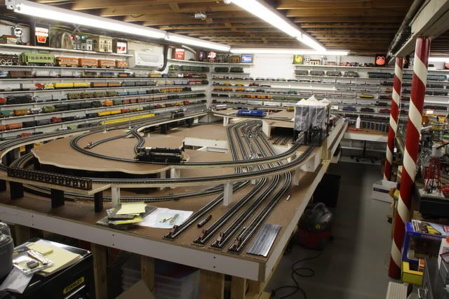
This looks nice and I like the looks of it. The whole room looks very nice as well and I like the look of it too. Got any bigger pictures?  Do you know the size of the layout?

The addition is ~9' x 21', the transition piece(beyond second pole is a negative elevation and is around 3' x 3'6" and the original layout(right of poles) is about 8' x 16'. In the picture above, note the Conrail engine and the plywood to the left with the subway car.

Transition piece image

Subway station(south end) is on the corner of the layout behind the mountain image 

Here is a picture taken from the far end. The Jay Street station is sitting the plywood I referenced above. image

Attachments

Images (3)
  • image
  • image
  • image
rtr12 posted:
rrman posted:
Mark Boyce posted:

My eyes gloss over when I see the wiring for some layouts here as well, and I have worked in Electronics for 40 years now.  I started my first job in July  1976 right after graduating from college, but electricity has always been a job to me, and nothing I want to do when I get home from work.    I like to follow the KISS principle when it comes to anything electrical.   

Even after 40 years, the second 'S' which stands for 'Stupid' fits me like to a Tee! 

Amen, brother!  Like you I too was in electronics 40+ years, paid well but am burnt out.  Would rather buy designed electrical stuff off shelf for layout and get back to running trains and scenery, rather than drudgery of design/build/debug/modify cycle.  My wiring is OK everything labeled but "it ain't like the pros here".

02261001

Oh, and to original poster, I like your layout design.  Sorry to have butted in here with my electronic non-sequitur.

This is great, that's my kind of wiring!

Did you by chance take this photo around Christmas time, in Clark Griswold's garage?

RRMAN,

I love the photo!!!

RTR12,

Yes, I think that must be Clark's handywork!  Don't invite him to help with layout wiring!! 

Last edited by Mark Boyce
It’s been sprinkling here all day, so rather than box up our lighted Christmas deer decorations, I’ve been working on the DIY benchwork design. I’m trying hard to follow AUBV’s example and think I’m close. As you can see, I expanded the knee wall to the 3 sides/back, but left a 6” overhang in the front. My thought is to add some shelves to display whatever BF buildings we won’t have room for in the village on the upper level or around the bottom level. I’ve also circled 2 legs that I don’t know are needed.
- Is the location of the knee wall okay or does it need to be moved back more?
- Are the legs needed?
- Does the bottom rail of the knee wall need to be full length in front or can the center be left out?
 
You will also see that I’ve incorporated some elevation changes for part of the over/under run as well as the tracks around the center. I no longer plan to add the vinyl lake with snaps to cover the center and I’m beginning to open up to the idea of spending more time in the middle.
 
Anyway, the purple benchwork drops 3” and the blue drops another 3”. I’ve attached a photo showing how I’d like to support these elevations changes, but I don’t know if they’ll be enough or if I need to add more legs. Since the drops are 3”, I’d like to make those sections using 1x3s and then the filler wouldn’t be needed.
- Thoughts?
 
I’m also thinking of squaring off the entrance to the horseshoe. The pieces that are on an angle would be straightened and located to support the lower bridge. The bridge and river, up to and including the dam, would be built on a simple slide-out platform supported by side rails just like a drawer. Again, it would be able to be locked in place from either the front or back. The river beyond the dam would be on a fold-down platform and the dam would cover the joint between the platforms.
 
I played with the track going around the center and the 3” drop gives me a grade of 3.3% on both sides leading back tot he switches. I don’t think that will be a problem for any of the 5-6 engines I’ll eventually have and the short trains I plan on running.
- Thoughts?

Attachments

Images (3)
  • DAZ2016-01-04
  • support
  • DAZ2016-01-04-3D
Last edited by DoubleDAZ

I agree with rtr12 about the legs with the purple circles.

I also agree that if it was me, I would fasten the outside to the wall.  I don't like putting a lot of holes in a wall in case I become disabled, or pass on, and leave my wife with a messed up room if she wants to sell.  However, in my case, my artist daughter has put so many shelves in the room I will use when she moves out, that I won't be adding that many more holes to the walls.  LOL 

I see the idea of the filler where the changes in level are, and I really don't know if it is necessary or not.  Someone else will have to comment.  On my HO and N layouts, I used the cookie cutter and graduated risers to change elevations, with no large area covered with plywood.  That was younger days; the flat surfaces with large areas built up are easier for me now, I think.

I kind of like the angled entrance, but certainly could be happy with it either way.  I do think it would be easier to forget the lake.  Just paint the floor blue, and pretend you are standing or sitting in a bass boat when you are inside the U.  Watching trains is far more fun than watching fish. 

You know why I am here, don't you?  Your room is virtually the same as mine, and the U shape with the bridges is what I have been thinking I will do.  I am sitting at my wife's computer right now about 5 feet from the door to my room that is right now jammed with daughter's art things.  I was hoping that young gent would give the daughter a ring for Christmas.  Shucks!  Well, he did just get a promotion, so maybe he will be stopping at the jewelry store sooner than later.  

rtr12 posted:

A couple of quick thoughts,

I think you need the legs with purple circles.

Have you ever considered fastening the perimeter frame for the table top to the wall? Looks like a lot of legs could be left out that way? Also, leveling with a bottom plate may be a concern? That's what gave me the thought of fastening to the wall?

I think I need the legs too, but figured I'd ask. I may need 4 more at the corners of the 2 purple sections in addition to the 7" joint supports I mentioned. I haven't thought yet about how many support blocks I'd need for the lower elevations.

Yeah, leveling is a question I should have asked, thanks.

Anchoring to the right/bottom walls is an option I'm considering and would require a lot less 2x material, but the knee wall keeps me from having to mess up the walls. And I know I could probably get by with legs and levelers instead of the knee wall, but I wanted to see what it would look like and mostly to see if I got the grid close to being right. Leveling a couple of 2x4 ledger boards for the grid tables to rest on would be easy though. I like the knee wall for the top wall because then I'd have a 4" board to rest that part of the layout on since I don't want to anchor it to the outside top wall there for sure. The knee wall and 2x4 ledger boards would give me wiggle room for making the layout square even if the room isn't square. Also, since the sides of the entry are only 48" or so, a leg with a rail would probably be enough support.

All good points.

Mark Boyce posted:

You know why I am here, don't you?  Your room is virtually the same as mine, and the U shape with the bridges is what I have been thinking I will do.  I am sitting at my wife's computer right now about 5 feet from the door to my room that is right now jammed with daughter's art things.  I was hoping that young gent would give the daughter a ring for Christmas.  Shucks!  Well, he did just get a promotion, so maybe he will be stopping at the jewelry store sooner than later.  

Mark, I agree with your points about the holes in the wall, the walls are already messed up from when our granddaughter lived with us. If the room is out of square a bit, I can shim the layout before I attach it to the wall.

The reason for the filler is because there would only be 1" in common between the elevations, adding the filler would give me 4", the same as I'd have if I made the elevation 4" and put them on top of each other the way AUBV did. At almost 69, I've pretty much nixed the cookie cutter approach for the same reason and all the filling in I'd have to do for landscaping, too much work for what I'm looking for.

When I said "squared" off, I didn't mean s1 long straight entrance. The bridge is 30" long, so it's support will have to be at least that wide and the entry is only 20: at the narrow part. The only thing that would be squared off is the benchwork, the platform would retain the angled appearance with a rock embankment or something like that. Good point though.

And, yes, I remember our spaces are a similar size and I'll be interested to see what you come up with. My goal and priority is a decent bottom level and a shelf for the BF display. Then I'll really see what I can do differently with the upper part, if anything. I waited 6 years for my daughter and granddaughter to move out and now I'm waiting on tiling, but there is a light at the end of the tunnel to get this thing going.

Next up I'll be asking about power requirements. I currently have a Z1000, DCS Controller and TIU.

Have you had a chance to play with the track changes to the upper level?

Have you considered a pt-pt on the upper level?

Not in order but- with knee wall construction it is very easy to shim/level under the bottom plate. In fact, if this is a basement concrete floor, I typically use feet made of azek. The are attached with screws (not from the underside) This keeps the wood from coming in contact with the concrete. 

If the entire structure is built correctly there is no need to attach it to the wall. If you want to use the wall, by attaching a ledger board(L-bracket) you would not need the 3 knee walls.

Typically, I build a perimeter knee wall. This layout might not need an entire perimeter knee wall and I can see a couple of ways to tackle this layout. I will try to do a drawing tonight.

Yes you can remove the bottom plate at an opening but I don't typically find any need.

Not sure I understand the 7" support 3" filler profile diagram.

If you are going to do a negative elevation for track, make one elevation change. If you then want to go lower for scenery, for a quarry or or canyon,  that is a separate issue but more localized. 


Last edited by aubv
First off, AUBV, I hope you and everyone knows I’m not trying to pit one design against another or offend anyone. I’m open to all suggestions and they all have pros and cons. One thing I’ve decided is that I’m going the DIY route, so I welcome all the suggestions and examples. This thread as a lot of good information and I thank everyone who has contributed.
 
Now, regarding you questions, here are my thoughts:
 
Track changes – I guess a little history is in order. When I first started designing the upper lever, I began with a simple oval. Then I saw a layout with a slanted bridge and changed the oval to incorporate that. However, I wasn’t happy with just the oval, so I added the reversing loops without the bridge. After adding the bridge to the bottom level, I decided to add it back to the upper level. I experimented with several configurations, including the one you suggested, but couldn’t come up with one I was happy with. Eliminating 1 or both of the reversing loops meant I couldn’t reverse the train after the first pass without backing up and I don’t want to do that. I then converted to a dog bone so I wouldn’t have to deal with 4 turnouts, but I’m concerned about the space the dual tracks need, so I may go back to the reversing loops.
 
Here are some renderings to show you what I think you suggested and how hard it would be to make the middle one work. The only one I think works is the 1st one with the curves, but even that required some minor location adjustments and I’d be concerned about the curves so close to the bridge entry points. It looks nice, but I really can’t imagine a railroad doing a bridge crossing like that, at least not very often.
 
Knee Wall – I assumed I’d have to shim the knee wall to level it and it’d be easy to make adjustments over time, so that is not an issue for me. The room is not a basement, but houses here are built on concrete slabs. The room is carpeted now, but that is being replaced with porcelain tile that looks like wood. AFAIK, I shouldn’t have any problem putting a wood knee wall on it, but the faux wood (like AZEK) is not a bad idea. And even though screws can be countersunk, it’s probably not the sturdiest to attach from the bottom into the end-grain.
 
I like the idea of the knee wall for the outside wall because of the Integra block. As I’ve said, I don’t want to put holes in that wall. Obviously, a ledger board/bracket approach for the 2 inside walls would be cheaper and less work, but doesn’t that then transfer noise to those walls? FWIW, the support for my 6x8 Christmas layout was a simple 4x6 frame made with 2x4 rails (top/bottom) and only 4 legs making for a 12” overhang all the way around. It was very sturdy and before I added the frame with legs, the foam-covered grid rested on a pedestal dining table the first year. The only problem with either approach was that it could be bumped fairly easily. I know I could build a 2x4 frame with a sufficient number of legs to support the layout, but I like the knee wall approach to minimize the number of legs around the inside. I’m a little concerned about where I’ve decided to lower the elevation,  more on that in a moment.
 
Bottom Plate – I get how it ties the whole knee wall together, but you don’t find it a hazard, especially for older folks?
 
7" Support – A photo you posted earlier (attached) shows how your elevation changes sit on top of each other and on top of a knee wall. The height of the wall seems to vary based on the height of the lowest elevation it supports. Other photos seem to indicate there might be a short wall in the front and a taller wall in the back of a section with 2 elevations. In this photo, I see a single leg holding up the back side of the front section. The section appears to be about 10’ with a 1’ overhang, more on that later. What I can’t tell from the photos is how the 2 elevated sections are attached to each other to keep the top section from moving. I assume there are a few 6”-8” pieces of metal or something on the backside. Or maybe they are glued?
 
At any rate, I don’t have a knee wall where I’m changing elevations and my elevated sections don’t sit on top of each other, they are offset and only drop 3”, not 4”. So, I needed a way to attach them. If they weren’t offset, I could just attach some 6”-8” pieces of 1x4s at several points. Since they are offset with only 1” in common, I didn’t think glue and screws would provide enough strength. So, I came up with the idea to add a 3” filler to provide a flat surface to then attach a 7” piece of 1x4 to and attach the lower elevation to the higher elevation. I did a better 3D rendering that might make more sense. I offset the 2 pieces so you could see them better.
 
Now, when it comes to support for the layout itself, it seems that if you can support that ~10’ section in the photo above with a single 2x4 leg, why couldn’t I attach the bottom side of my layout to a ledger board on the inside wall and then support the top side of the layout with 3-4 legs (and bottom rails for stability) along with the 6 other legs I have around the inside of the layout? Again, I like the knee wall to keep from putting holes in the outside wall and to avoid transferring noise to the inside walls. It’s not unlike dual walls between apartments, duplexes, etc. I guess I'm curious as to why you use knee walls rather than anchor to the studs.

Attachments

Images (3)
  • bridge-alt
  • AYBV
  • supports
Last edited by DoubleDAZ

First, the discussion about knee walls came about because of a picture(mine) showing what can be accomplished with negative elevations. It wasn't to suggest the use of knee walls is how this layout should be built. Considering, the interest I did a quick design that will work very well. However, I will not be offended in any way if you think it doesn't work for you.

That said, knee walls have some big advantages but are not to everyone's liking. I can only tell you what I would do.

I did this design to illustrate how it might be accomplished.

The design has 7 pieces for the actual table top but this includes 3 pieces you build twice. There are 14 knee walls(2x3's) sections  4-8' 4-38" 2-29" 2-81 2-21" (dimensions approx)) Part of the design takes into account you have walls on three sides. 

The advantage of this, you can build the pieces, then assemble. No cutting and virtually no drilling for assembly. image


Track changes-

You changed the entire geometry of the reversing loops, by adding short sections of straight track, 1/2 curves etc. The reasoning for my track change suggestions, by rotating the bridge, the bridge may not feel quite as imposing in the center of the layout up 12"(?) in the center. It kind of blocks the view to buildings on the back wall. It might lead to moving the actual town to both sides of the bridge. The north side of town might be in front(west)of the track and the south portion behind or east of track. This could then easily free up the east wall area for scenery, among other things.

Again, not all of my ideas are good.

Attachments

Images (1)
  • image
Last edited by aubv
  1. DoubleDAZ posted:
.....At any rate, I don’t have a knee wall where I’m changing elevations and my elevated sections don’t sit on top of each other, they are offset and only drop 3”, not 4”. So, I needed a way to attach them. If they weren’t offset, I could just attach some 6”-8” pieces of 1x4s at several points. Since they are offset with only 1” in common, I didn’t think glue and screws would provide enough strength. So, I came up with the idea to add a 3” filler to provide a flat surface to then attach a 7” piece of 1x4 to and attach the lower elevation to the higher elevation. I did a better 3D rendering that might make more sense. I offset the 2 pieces so you could see them better.
 

In this case I would stack one level on the other. You can use a cleat to attach the two sections. See Yellow small blocks in diagram, one is highlighted. This will give you a straight vertical wall, that lends itself to doing scenery.

Last edited by aubv

AUBV, I took your knee wall photos as a suggestion of how you would build the workbench if it was your layout or you were commissioned to build it. However, I didn't assume you were saying it was the only approach or even the best approach. I admit I took the term "knee wall" to mean a "wall" as opposed to a more standard "fence" with rails and legs like your latest design. Your rendition is very close to my original L-girder design as far as location of the rails and how the layout overhangs, but is much simpler than the full L-girder design I had.

I am wondering about working work with an 8' span using a 2x3 on its flat side as the top rail though. Couldn't it sag over time? Or will attaching the grids make the whole assembly rigid enough? When I built my table frame, I turned the 2x4's upright for more rigidity, but because it had to be portable, I didn't even attach the grid to the frame.

I would never have thought to do a separate "fence" at the lower elevation to support the purple sections, but it makes perfect sense and gives me the overhang I kind of wanted all the way around the accessible parts of the layout. I like how you simplified the grids too and divided them into sections. I didn't go back and look at that after I changed the elevations and I should have, so thank you. I think this a nice compromise between the knee wall and what I call a fence. I still like the idea of supporting the entire layout as a large "table" vice anchoring to the wall.

Now, when it comes to stacking, I keep thinking in terms of 1x4s when I really need to think in terms of the grid depth "plus" the sub-roadbed. In other words, if I use 1x4s with 1/2" plywood, I get a depth of 4". However, if I use 1x3s with 1/2" plywood, I get a depth of 3". So if I want a 3" elevation change, I need to use 1x3s and 5 1/2" cleats. It just dawns on me that I never asked what you use for sub-roadbed. This photo suggests 1/2" something, but I can't tell if it's painted plywood or something else.

roadbed

The only thing missing in your example is the 2nd lowered elevation (in blue) I have in my latest design. The 1st drop deals with the over/under, but the 2nd drop of another 3" accounts for negative landscaping in that area. I can simply adjust the framing in that area and follow this example you posted earlier:

drop

Again, you have been most helpful and I thank you for your patience.

Attachments

Images (2)
  • roadbed
  • drop
aubv posted:

Track changes-

You changed the entire geometry of the reversing loops, by adding short sections of straight track, 1/2 curves etc. The reasoning for my track change suggestions, by rotating the bridge, the bridge may not feel quite as imposing in the center of the layout up 12"(?) in the center.

I'm sorry, but I simply couldn't figure out any other way to make things fit. It wasn't as simple as moving 1 switch further around the curve and replacing the other with a RH. The geometry of O31, O54 and O72 switches just wouldn't connect. However, as I was composing this apology, I decided to take another look and saw what I was missing. I completely neglected to consider the very reason I want to use ScaleTrax, their FlexTrack. I got hung up on trying to make sectional track fit and it simply doesn't. So, rather than try to reconfigure my loops, I started with the bridge/connecting track/switches on an angle. When I placed them across the divide, that's when I realized I could complete the loops using FlexTrack.

I did understand the rationale for turning the bridge sideways, just couldn't see how until now and that is my next project. In the meantime, I did some work on the benchwork and I'll post that separately. It won't include changes to the bridge geometry, but now that I see the light, that won't be a problem to change. I just hope you'll continue to help, I think I'm very close to finalizing the design, so I can start building once the tiling is done.

Last edited by DoubleDAZ
Well, I've spent parts of the last few days working on my design and I hope I got the gist of all the suggestions I've been given, I certainly appreciate the help. I know this is probably drudgery for some, but for me, it's a lot of fun and I enjoy the challenge.
 
The benchwork layout differs only slightly from what AUBV posted a few days ago. Initially I got hung up on using 1x4s for the grids and trying to figure out how to support the negative 3" elevations. That's how I came up with the idea for a staggered cleat with a filler. I've all but decided to simply use 1x3s and standard cleats to tie the levels together. The photo still shows the sections being staggered, but that's just for visibility.
 
AUBV had things separated into 7 sections, but I changed it to 8 to accommodate the 2nd negative level (blue). I show a rail (yellow) beneath it for support, but it's so small, I think can probably make do with just a series of cleats. I also made it smaller than it was in the original design because I wanted the tracks along the back wall to be well-supported and they aren't part of that section when it comes to landscaping. I'm not talented enough to paint a scene that looks like it's fading in the distance, so I'll probably put up a wall or something. Maybe I'll go out in the desert and take a panoramic photo of a wash from a distance to see if I can use it as a backdrop. If nothing else, I'll just paint it black.
 
Another change of note is what I did with the over/under. It's hard to see in 2 dimensions (and the photo shows the wrong one on top by the #7), but I swapped them around and reconfigured the tabletop for that level as well as how the track flows over it. It'll make a little more sense when you see the other views. With the negative elevations, I was able to lower this level, but then I almost forgot about the dual tracks along the back wall it would cover. I solved that by cutting the level short and not letting it go all the way back to the wall. That way when I remove the village sections on top, the access will be clear to deal with derailments, etc.
 
Since I was able to lower the 2nd level with the elevations changes, I was also able to lower the top level. Then I thought about what AUBV said about visibility. Even though I intend to turn the bridge on an angle, I thought I'd further help with visibility by raising the village level 3". That way the trains will pass in front without obscuring the village. I'll place a depot off to the right on the train level and simply landscape a hill to the village level. I've attached a rendering showing all the elevations.
 
It's still based on a base of 34", but now that I've been able to lower the village to 43", I may change everything to use a base of 38"-40". If I add Homasote roadbed, I may have to add 1/2" to some. When looking at the elevations, bear in mind that the only place I think clearance is needed is the over/under. I think I have all other tracks offset to where the visible parts of one level don't require clearance. FWIW, there are 6 grades...top to bottom 3.2%, 3.9%, 3.2%, 3.2%, 3.6% and 3.4%
 
I'm still looking at the "knee wall" configuration, specifically the rail supports and legs (blue). Right now I have separate legs for each section of rail and the longest rail is 8'. If you look at the 2 rail sections along the back wall, you'll see that I added a leg in the middle of the 8' section. When I built my table frame, I set the 2x4s upright and wasn't concerned about sagging with the 8' span. However, laying them flat bothers me a little and I feel the extra leg can't hurt, though it is another leg to adjust when leveling.
 
Next up I'll be reconfiguring the top loop-to-loop to angel the bridge as AUBV suggested. I'm not as concerned with visibility, but I like the look of the bridge on an angle, the way I wanted it in the beginning.
 
As always, I welcome comments and even more suggestions.
 
Benchwork with level 1 track locations.
v1.7-benchwork
3D view to show elevations.
v1.7-3D-1
Latest version of full design with track 3 sidings added to loops.
v1.8
Latest version of level 1 showing siding added to bottom of track 2, the over/under.
v1.8-1
Head-on 3D view of full layout.
v1.8-3D-2
Angle 3D view of full layout.
v1.8-3D-3
Base level 3D view of bridges in relation to village behind the upper bridge.
v1.8-3D-4
Rendering showing various elevations.
v1.7-elevations
 

Attachments

Images (8)
  • v1.7-benchwork
  • v1.7-3D-1
  • v1.8
  • v1.8-1
  • v1.8-3D-2
  • v1.8-3D-3
  • v1.8-3D-4
  • v1.7-elevations
Last edited by DoubleDAZ

Thanks, RTR12. I wish it were more complicated and now that I have this pretty much settled, I'm still going to play around with connecting the 2 sets of track on the bottom level, at least in RR-Track, while I wait for the tile to be installed. I've got 1 loop on the top level reconfigured with FlexTrack and I'll get the other done in short order. I'm not sure it changes the view enough though to make it worthwhile, so I'll play with the simulation a bit. I never played with the size of the loops either after I converted to the dogbone. I need to figure out how level 2 is going to be supported and make sure the supports don't interfere with any track on level 1. I'm sure I'll find other things along the way as I build. The main thing is I've got a design I'm happy with.

There might be a setback though. I just got word from the doctor that I have a meniscal tear in my right knee joint. They'll be calling to make an appointment with the ortho folks and we'll go from there. We leave on vacation soon and then have another one a month or so after we get back, so even if the tile gets done mid-month next month, I might be recovering from the knee procedure. Oh well, life goes on, right?

Dave,

First off, if your knee procedure is anything like mine was 9 years ago, you will be up an about in no time!  My tear was shredded up from rubbing back and forth over the arthritis lumps, so he took out everything that was bad.  Of course I was only 50 at the time, so maybe it was easier recovering than it would be now.

On to the layout design.  Thank you for posting the three dimensional views, the front view looking into the opening, and the benchwork cross section.  That helps me visualize it a lot better.  It looks even more inviting than I had imagined looking at the plans and first 3d view.  Yes, I see now where the idea of the river insert would look better than the 'grand canyon' view I suggested with the blue painted floor.  I realize that is a minor consideration now.  I know you are interested in having about 3 trains continuous running at a time, and have one parked on the siding in the back.  Do you have any interest in adding a passing/parking siding on any of the other loops?  If you are like most of us, you have more trains than you can run at a time.  Maybe it is just me with my arthritic fumbley hands, but I don't like moving locomotives from shelf to track and back.  I envision having someplace to park all my heavy locomotives at least.   Just a thought.

I would say that with being happy with the design, the battle is won. From what little I know, I do think connecting the loops in some manner would be a really nice touch and something that would a lot to the plan. However, doing that may be a difficult task, but if there is any way possible I would definitely try to do it. As for the knee, good luck there. Hopefully the repair won't be too bad and you will be back to normal in a short time.

Mark Boyce posted:

Dave,

First off, if your knee procedure is anything like mine was 9 years ago, you will be up an about in no time!  My tear was shredded up from rubbing back and forth over the arthritis lumps, so he took out everything that was bad.  Of course I was only 50 at the time, so maybe it was easier recovering than it would be now.

On to the layout design.  Thank you for posting the three dimensional views, the front view looking into the opening, and the benchwork cross section.  That helps me visualize it a lot better.  It looks even more inviting than I had imagined looking at the plans and first 3d view.  Yes, I see now where the idea of the river insert would look better than the 'grand canyon' view I suggested with the blue painted floor.  I realize that is a minor consideration now.  I know you are interested in having about 3 trains continuous running at a time, and have one parked on the siding in the back.  Do you have any interest in adding a passing/parking siding on any of the other loops?  If you are like most of us, you have more trains than you can run at a time.  Maybe it is just me with my arthritic fumbley hands, but I don't like moving locomotives from shelf to track and back.  I envision having someplace to park all my heavy locomotives at least.   Just a thought.

Mark,

I turn 69 in early March, so I expect it will take a bit longer to recover, but I assume it will depend on what they tell me the damage is and how the procedure goes. My wife will see to it that I do what they say, so I'm not concerned, other than I don't want to have to cancel any trips. We can postpone the first trip, so we'll just have to see what the ortho folks tell me. Hopefully, I'm not underestimating what it will take. 

At the moment, I'm getting back in the hobby late and have only 1 train, the 2013 MTH RailKing 4-6-0 Christmas Passenger Set. My plan is to buy 2 diesels before Christmas this year and "up to" 3 more over the next couple of years, saving the Christmas set for the holidays. I'm not a collector, so there's little danger of me buying any more than that. The goal is to be "able to" run 2 trains on each of the 3 lines, but most often I expect to be running 2 on the main line with the hidden siding and 1 on each of the other 2 lines. The reason for the 2 bridges/crossovers is to provide a way for 2 trains to pass each other. I get the desire to "park" engines vs taking them on/off, but in my view the space is too small for more sidings and the addition of the elevation changes doesn't help. I can park a train on track 1 on the hidden passing siding and that's always seemed good enough.

However, after reading your comment, I decided to take another look and found 3 places I thought I could do something with. I peeled back the levels and swapped in a switch at the south end of the over/under to run a siding beneath the houses there. I then took another look at level 3 and swapped out 2 more curves to add switches for 2 smallish parking sidings inside the loops. Between the 2 of them, I should be able to park an entire train; cars on 1 side, engine/tender on the other.

I still need to do some measuring so I can decide on keeping the dogbone or converting it back to a loop-to-loop. The village display shelf on level 4 will be added as part of the initial build, but the track on level 3 probably won't be added until next year, so I have some time. Even though I was trying to limit the number of switches, I'm leaning toward the loop-to-loop. I think it will look better with a single line in front of the village.

I've updated the photos in my earlier post, so check them out.

Last edited by DoubleDAZ
rtr12 posted:

I would say that with being happy with the design, the battle is won. From what little I know, I do think connecting the loops in some manner would be a really nice touch and something that would a lot to the plan. However, doing that may be a difficult task, but if there is any way possible I would definitely try to do it. As for the knee, good luck there. Hopefully the repair won't be too bad and you will be back to normal in a short time.

Thanks, I'm sure I won't be out of commission long. And I'm not giving up on joining the 2 sets of track on level 1, but I'm going to wait until I get the benchwork built and the track drawn out on the tabletops. Then I'll be able to "see" clearances better than looking at them on a computer screen.

Well, I must not have a life because I went ahead and converted the dog bone on the upper level back to a loop-to-loop and need some opinions. Not to influence, but the new version would allow me to build up more of a mountainous terrain and it wouldn't use as much space in front of the village. I'm a little concerned that the upper bridge is too close to the edge, but I guess I can add some straights to move the loops forward a bit.

I noticed I had covered my over/under, so I changed the terrain for level 2 a bit. I also added a few terrain elements between the levels to fill in the empty space to simulate a hillside. There's probably better ways to do that in RR-Track using contours, but I've never figured those out. FWIW, even though the Bedford Falls Village Collection will be used for buildings, it's being transported to Arizona where the bottom terrain will be desert with a mesa on the NW part of level 2 leading uphill to the village. The SW will just be a hill going up. I can see it in my head, but it's going to be a major undertaking to bring it to some sort of life.

v1.9

v1.9-3D


Attachments

Images (2)
  • v1.9
  • v1.9-3D

image

A few other thoughts, 

If you eliminate the north reversing loop,  you might then have a better view of the lower level tracks on that side of the table. You could accomplish this by using two bridges or use one bridge to a butte, then a simple girder bridge on the other side. The butte could have tunnel openings to accommodate the lower level track.


Attachments

Images (1)
  • image
aubv posted:

A few other thoughts, 

If you eliminate the north reversing loop,  you might then have a better view of the lower level tracks on that side of the table. You could accomplish this by using two bridges or use one bridge to a butte, then a simple girder bridge on the other side. The butte could have tunnel openings to accommodate the lower level track. 

I didn't quite understand this suggestion the first time, so I threw together a rendering to see if I get it now. If I do, I certainly like the added visibility, but don't really like giving up the reversing loop. IMHO, if I give up one, I might as well give up both, so I did a rendering of that too.

Surprisingly, I can see the advantages in both visibility and landscaping possibilities. This lets me locate the mountains along the sides and use a mesa/butte to deal with the bridge. Before I commit though, I want to change the O54 curves to O31 and see if I can work in a passing siding on the south side. That way I can run 2 trains in opposite directions and still get the look I'm after. I'll also need to clean up the tracks north of the bridge.

Just when I thought I was done, you throw me a curve, but the more I look at it, the more I already like it, so thanks for bringing it up one more time.

v1.9-alt

v1.9-alt-3D

v1.9-alt2


Attachments

Images (3)
  • v1.9-alt
  • v1.9-alt-3D
  • v1.9-alt2

Dave,

I am with you, it is either 2 reversing loops or none at all.  A friend showed a plan on Facebook yesterday, and someone told him he needed reversing loops.  He is like you and me, doesn't have a lot of room.  He told the guy he would rather have the space for other things than reverse trains.  I told him that was my philosophy too.  I like this plan.  You want the upper level, but you don't want to make it hard to see the detail of the lower level.

aubv posted:
I wouldn't be to quick to eliminate the second reversing loop on the upper level.

May I ask why? I know I could at least reverse trains when I want to, but I've been trying to envision when I'd take the time to back one up through the loop to do that and if it would really make a difference to me. I'd like to see trains coming and going in opposite directions, but I think I can accomplish that with a passing siding (if it's long enough). Mind you, I don't mind keeping the loop, I just can't see myself using it. But then, I have the same reservations about the passing siding, though it should at least be long enough to park a short train, longer than the loop. Keeping it certainly is the cheaper alternative. My vision is to run a short 4-4-0 General or 4-6-0 Santa Fe  passenger train and then the 4-6-0 Christmas passenger train during the holidays. All I'm really after right now is to be able to park the Christmas train and run it once in awhile just to keep it ready. I can accomplish that with just a hidden siding going east along the south wall. Heck, I might even be able to so something with elevations to raise just the track in front of the village and run a siding down beneath the village. That would raise the village that much higher than the bridge and increase the view even more. I've been busy with some other things today, so I haven't gotten time to play with the design. Still, I'm curious why you think I should keep the loop. I think at one time you suggested I consider doing away with both, unless I misunderstood the comment.

Mark Boyce posted:

You want the upper level, but you don't want to make it hard to see the detail of the lower level.

That's been my problem with the upper level all along. I've always felt the loop took up too much space given how much higher the level is, but until AUBV's post, I couldn't envision how to change it by angling the bridge and deleting the north loop. Now that I've seen it, I like the added visibility, but I don't want to delete both if there's a good enough reason to keep the south one. I don't mind dealing with the size on that side because it's better located relative to the lower level tracks, etc. I can go either way on the south loop. In fact, after talking about it now, one of the alternatives I'm going to try is keeping the loop and still add a siding along the south wall. I never pass up an idea and it only costs some time to experiment, something I enjoy doing anyway.

Well, I didn't get any comments on my last version, so I started messing around with the benchwork design. Then I read a post where someone mentioned using curved switches for a siding. So, I played with that a bit before I read another post that lead me to trainroomgary's article in issue 278 showcasing his shelf layout and some You Tube videos. I really liked how he connected his tracks in a relatively narrow space and it got me to thinking once again about connecting the tracks on my layout. We were all packed and ready for our trip early, so I spent the afternoon completely revamping my design. I felt what I had done earlier was getting more involved than I wanted and this new design is much simpler with quite a bit more functionality. I'll probably get some time to mess with it more while we're in Florida, but thought I'd post what I have so far to see if I get any feedback. I intend to add 2 more shelves like Gary did. ANd before I go any further, I'm going to put it in SCARM.

shelf v1.0

shelf v1.0-3d


Attachments

Images (2)
  • shelf v1.0
  • shelf v1.0-3d
Files (1)

Dave, your

I have seen the pain you've been going through wrestling between enough space for all of your collection and enough track for an interesting run. I just ran sim on the lower level file that you attached. It's a cool run. It took almost 3 minutes at scale 40mph to run  the whole layout and finally back out to the outer loop in the opposite direction.

it flows really nice. Running two trains would make it interesting when changing tracks on the fly. No cornfield meets permitted!

I am working on a shelf addition on a two level layout design, also, that needs more space for a collection of Christmas buildings. It works. I thought go up. We are viewing the shelf as being landscaped to look like a cliff or hill to make the transition the layout level blend and a tunnel underneath as it must attach to the table. No wall nearby.

Thanks, Carl. I never did get around to measuring the buildings, but it's not really about that anymore. My consternation has been with having most of the buildings on the top level and with all the changes, I think I've covered up too much. Although I liked what I came up with, I was getting more concerned about access to the hidden tracks and switches. I also never liked not being able to connect the bottoms sets of track. I tried, but I was blinded trying to make it work within the design I had vice starting from scratch. Then, too, I was afraid I was letting the benchwork get more involved than it needed to be for the size of my layout.

Then I saw a post by Alex in Darren's thread about the design used for the legs he was using on his layout and I played with that for a bit. I've also been watching Tom's build and couldn't help noticing how simple his benchwork was. Somewhere along the line I saw a post by Gary and that led me to his article in PGR and his You Tube video. I was struck by how similar my basic design was and how he was able to pack a lot of action into relatively narrow shelves. When I saw the video, I knew I needed to start from scratch to see what I could come up along the same lines for my layout though I had no intention of giving up my design.

However, once I started something that mimicked his runs, I knew I was on to something that I might actually like. The biggest thing I like is I'd have access to everything. Next is being able to run trains over all the track on level 1. I miss my over/under, but I can always do a folded dog bone on one of the other levels. I particularly like how he used standard shelving for levels 2 & 3, no pretense that they are anything but simple display dog bones that happen to be nicely landscaped. I think my design for level 1 has enough space for the main Bedford Falls Village and I can have mini-villages on the other levels.

I don't quite know what legs I'm going to use. I think the grids I've got will work okay. There are two 54"x54" sections at the front of the layout, two 30"x54" sections in the back and two 30"x60" sections along the sides. There is also an 18"x30" section connecting the back that will actually get sized to fill in the gap once the others are in the room. For crossmembers I simply divided each section into thirds. Right now the legs are made using 1x3's to form an "L". These are then screwed to the inside of the 4 corners on the front and back sections making a total of 16 legs. The side sections will simply be bolted to the front/back sections on either side. The small section may end up being nothing more than a piece of plywood with a 1x2 face to form the base of a river/gulley. When it comes to the other 2 levels, I intend to pretty much just copy Gary's methodology and I may even use 3/4" plywood for the same reasons he did.

We're in Fort Stockton TX tonight, Scott LA tomorrow and Jacksonville NAS FL for the 3rd night on our way to Cape Canaveral and Key West. Not sure when I'll get to play with the design some more, but time for finalizing things is approaching. When we got back home, the tile will be installed and then I'll be ready to start. Construction will be interrupted again by another trip to Georgia, but I hope to get the sections built before we leave. Then I'll need to order some track and see when it can be delivered, unless I find some while on vacation. I'm hoping to get to Legacy Station in Atlanta, but I don't know if they stock ScaleTrax. If not, we might make a run over to Burbank to the LHS there after I see if they have some. They're the ones with the ScaleTrax layout in their shop.

Well, I'm on vacation in Cape Canaveral FL and begin the trek home tomorrow morning with a 2-night stop in Albany GA for some college baseball with our oldest grandson (19). Delivery of tiles for the rest of the house is scheduled for Wednesday with installation to begin a week from Monday. We'll have to take some time to put the house back together, we have stuff all over the place, and then I'll finally be able to make the first cut and drive the first screw. I haven't had any time to finalize my layout design, so my plan is to work on that as much as possible over the next 2 weeks.

I'm 99% positive I've got the basic benchwork real estate finalized, so I'm ready to start construction of that. Someone posted a comment about ripping 3/4" plywood into 3 1/2" wide strips to minimize warping and I've seen people mention that before. My layout is only 10' 8"x12', so I think it would work. I'd get twelve 1x4x8's from a single sheet and wouldn't have to dig through the piles at Lowe's or HD looking for boards that are straight now and would probably warp rather quickly once inside the house. I had trouble with my previous temporary Christmas layouts, but I used pine and didn't really care all that much.

I still plan to cover the benchwork with 1/2" plywood, but I'm not sure how to attach it. It seems to me that screwing the tops into the plywood strips on edge won't make the strongest joints or am I being overly concerned? I suppose I could use angle brackets, but that just adds to the cost. Maybe I need to find that post and ask some questions there before I settle on this method. I think it might have been Tom Tee who mentioned it. I'm not trying to be cheap, but I don't want to waste money on poplar 1x4's if ripped plywood will work just fine. All these options are why I considered Mianne and maybe I still need to send them my design and see what they can do at what cost.

Add Reply

Post
The Track Planning and Layout Design Forum is sponsored by

AN OGR FORUM CHARTER SPONSOR

OGR Publishing, Inc., 1310 Eastside Centre Ct, Ste 6, Mountain Home, AR 72653
800-980-OGRR (6477)
www.ogaugerr.com

×
×
×
×
Link copied to your clipboard.
×
×