Dale


I have studied this a couple of times  and think it can work but I have to admit I am a little intimidated - at best, my electronics experience is at the level of Greenberg's Wiring Your Lionel Layout Volume 2 although I do continue to study this and other blogs and websites.


One complication: in reality, Blocks 1 and 2 are a big part of one of the ramps, but I think can be addressed.  Thoughts? 


One request (and I hope I am not over-reaching here):  could you create a parts list which I can use to buy the parts?  Don't care which supply house, I will adjust for the number of actual blocks.  I have seen posts from other people with little experience having the same problem - we get the approach, but get lost when looking at the long list of part choices.   Even simple stuff like DPDT or SPST toggles you wonder whether you are getting the right thing.  That's why as a novice I am confident putting in your design for circuit breaker / TVS -- you listed parts, included pictures.


Which also underscores how thankful I am to you and others who support this blog -- will post pictures and videos when I get things running!


Thanks again

Originally Posted by Jbb:

Dale


I have studied this a couple of times  and think it can work but I have to admit I am a little intimidated - at best, my electronics experience is at the level of Greenberg's Wiring Your Lionel Layout Volume 2 although I do continue to study this and other blogs and websites.


One complication: in reality, Blocks 1 and 2 are a big part of one of the ramps, but I think can be addressed.  Thoughts? 


One request (and I hope I am not over-reaching here):  could you create a parts list which I can use to buy the parts?  Don't care which supply house, I will adjust for the number of actual blocks.  I have seen posts from other people with little experience having the same problem - we get the approach, but get lost when looking at the long list of part choices.   Even simple stuff like DPDT or SPST toggles you wonder whether you are getting the right thing.  That's why as a novice I am confident putting in your design for circuit breaker / TVS -- you listed parts, included pictures.


Which also underscores how thankful I am to you and others who support this blog -- will post pictures and videos when I get things running!


Thanks again

I can do that. There are two reservations I have about the design though. 


First, holding in E units is tricky,I can not guarantee it will work either with rectifiers or wire wound resistors. . You may have to lock the locos in forward.


Second, the whole thing depends on the twin coiled latch relay circuit working dependably. I would construct that circuit first,,if that works,everything else is straight forward. 


The voltage on the ramp close to blocks 1,2 will change when the first wheels of the train contacts block 2. 


I can not comment on the Greenburg guide,I have never read any train wiring books,I design my own circuits. 


Toggles depend on how you are switching. If the layout is large,you may want to consider relays.Shown here


LINK


On the protected loop,to switch off power all you have to do is activate the relay coils with a switch and power will be cut.


Dale H

Originally Posted by John A DeAlto:

Hi, What is it your tyring to accomplish here ? I'm not asking about his drawing. what is it that you would lik for train board. THE Drawngs only he can understand. 

They need to make his Drawings alittle more simple and user friendly.


Thanks, John


kb2agpjohn@aol.com or a call on my cell phone 848-992-2157 

Hello John


I know at first glance the drawings seem complicated. In reality it is a combination  simple binary switching circuits combined with basic electrical applications.Relays really are switches activated by a magnetic coil. They have been around a long time and there is no real mystery to them. They make and break one or more circuits when the coil is powered. In this case the coil circuit is completed when the train occupies an electrically isolated area on the track. A section is occupied or it is not. The switching contacts are on or off,all binary concepts. When wiring this thing the wires will follow a logical pattern. If you look at the wires they are color coded and all go to specific places. 


I presented the drawings in sequential steps so if the reader follows them, hopefully he/she will understand how it works. I drew them that way as I approached the problem. I have to solve the issues too and think about it. Everything is usually solvable but it is not always obvious.  Other than the reservations I previously have expressed with the latching relay circuit and preserving the E unit, it should work if wired correctly. Among other things,I am a retired pinball repair person. This is by no means the most complicated circuit I have seen.Old pinballs have step switches and mechanical 10 digit scoring reels. At first it looks complicated but if you divide it into sections everything does something and the circuits work in unison. Most all circuits are really combinations of simple basic circuits as I said. This is even true with IC chips and computers. Because Jon's layout is bidirectional it is a little more complex than what I use on my layout.In this case the circuits are simple but there are a lot of them but they still work in unison.


 Jon asked a question in his first post. If you read it,it describes what he is trying to do. I understand,I think and am trying to help to the best of my knowledge. I already do much of what is described successfully on my layout so I know it works,at least for me when I do it. 


So for his layout he needs maybe 30+ relays,some barrier strips,some diodes,some capacitors,some wire etc. These are all common generic electrical components. It is not plug and play you have to do a lot of wiring. Run color coded wire from the track

sections to barrier strips and number the blocks. From there all can be wired from a common central board,though you can also position relays along the layout. Since the layout is large we also have to consider voltage drops so we need adequate wire size.  Most likely you are looking at around $300-$400 in material and some evenings of labor. Hopefully it is a labor of love. That is maybe a similar cost and labor of converting 2 locos to PS2 or something on a command layout. Conventional is much cheaper in this respect and you won't have shelf queens. Most of these parts I even already have in my parts bins because I make my own circuits.I am still doing a second layout. 


Dale H

Last edited by Dale H

Jon


After looking at my prints again I still have some problems I did not think of with the ramps. With 2 trains running the rollers will jump out the voltage dropper and give the same voltage to the other train I think. I have to re think this so put it on hold for now. Sorry. Not sure I can get that aspect to work.


Dale H

Before we started this long chain, my thought was to put a direction switch on the control panel which would reorient the block control and ramp power controls to clockwise or counter clockwise set-up.  Nowhere near as elegant as the solution we have been discussing but avoids the detection issue.  Other thought I had was using a more sophisticated detector technology -- not typical for conventional o gauge but there must be motion detectors of some form out there (again, way beyond my experience set).


Thx

Problem I had in my original design was that I did not consider rolling jumping. Because of the complexity I tried to avoid it,but it seems necessary here. With 2 trains running at once rollers would jump the voltage dropper and the other train would receive the same power. So,first I will draw a revised version of the layout with 10 blocks instead of 12. Unlike the first diagram, each block will have an insulated center rail and insulated outside rail so there are 10 of each. The 10 is arbitrary,you can make more or less.  The entry blocks,1 and 10 can be about 2 feet long or longer. I think you said the grade is near block 1 and 2, so block one needs be short as possible maybe.  The rest of the blocks are 1 train length or longer. Click on any diagram to enlarge.


Jon 12 new block diagram


Now the task is to eliminate roller jumping when the train travels in either direction. We need to add 10 contacts on the twin coiled latch circuit. This can be 2, DPDT relays or whatever. The coil circuit is not shown but they are simply in parallel with the other relay,no capacitor. If you want to eliminate the automatic detection system and just use a toggle switch you can,the circuit remains much same where the toggle activates the relays instead of the twin coiled latch relay.


Now for block power distribution and collision avoidance. You will then need 18 relays,20 are shown for completeness. The extra ones possibly used for the other side of the loop. Only 10 relays will be used at a time, 10 for clockwise and 10 for counter clockwise. Which 10 decided and enabled by the latch relay circuit detecting train direction. For clarity the circuit is shown in 2 diagrams,but it is 1 circuit. If trailing cars are altered as discussed before, this circuit should eliminate roller jumping. If that is the case 4 taps of a ZW can be used or the voltage dropper diodes as previously discussed.


 In the first diagram a train entering clockwise has flat voltage on block 1. When the front wheels of the engine land on block 2, Capacitor discharge throws the twin coiled latch relay (discussed previously,may have to revise this system so this happens or just use a toggle to select loop direction before train enters.) in the proper clockwise direction (if it is not already).  Block 1 is disconnected from the track power and connected to block 2 and receives whatever power block 2 has. Block 2 will have uphill power unless block 4 is occupied. If it is, stall power can be fed through the unused relay contacts,or no power if the train is locked in forward. The stall power could possibly maintain the E unit but this is tricky. Locking in forward is more reliable. As the train moves through the loop, the train will receive power from the lead block, the relay contacts disconnect the trailing block from power and connect it to the lead block. Power will be cut to the block 2 behind it. When the train reaches block 4,rear collision avoidance is established. Block 4 cuts block 2,block 5 cuts block 3,etc. When the train reaches block 9, there is no longer a train in front,since that is outside the entry point. Further relays in that section could possibly be used. Block 9 and 10 could also be switched off manually with a toggle. Any train behind it would automatically be switched off. In the second diagram the counter clockwise direction is shown. It works like the first diagram only in reverse.


Jon 13 block power circuit revised


Jon 14 block power ciruit revised


The block signals can be circuited the same way as previously described. You may have to change the block numbers a bit to accommodate the new drawing. Discard the previous diagram for block power distribution. Roller jumping must addressed as described. If it is not,you will have erratic operation if using the diode dropper and risk transformer damage if using more than one ZW tap to the same loop. You should not connect A and B for example (which can be done with rollers) if set at different voltages.


Sorry this is so involved but I do not see an easier way. I think I drew it correctly but check it out. If others have ideas feel free to present them.


Dale H

Attachments

Images (3)
  • Jon 12 new block diagram
  • Jon 13 block power circuit revised
  • Jon 14 block power ciruit revised
Last edited by Dale H

Dale


Can you expand upon the following paragraph from your prior posting - not certain I follow


"Now the task is to eliminate roller jumping when the train travels in either direction. We need to add 10 contacts on the twin coiled latch circuit. This can be 2, DPDT relays or whatever. The coil circuit is not shown but they are simply in parallel with the other relay,no capacitor. If you want to eliminate the automatic detection system and just use a toggle switch you can,the circuit remains much same where the toggle activates the relays instead of the twin coiled latch relay."


Thanks

You said in a previous post you simply want to flip a toggle to select loop direction instead of having the train detect it. The circuits I posted eliminates roller jumping. Roller jumping would prevent separate voltages of the ramps and flat surface as the taps could be cross connected,put in parallel by the rollers. Which direction the trains run is hopefully switched by the latch relay automatically as the train enters the first block in the loop or can be manually selected instead before the train enters with a toggle which will turn on or off a group of direction relays,the same way the twin coiled latch relay does. Ten contacts from them are shown in the above diagrams . The latter choice may be better in operation. When the loop is empty you can flip a switch to achieve proper direction orientation of the loop and enter one or more trains in it,and  when the approach block signal is green.  Once the train enters and gets to the 3rd block,There will be collision avoidance automatic from a train behind if you enter a second train. If you use 2 push buttons and a latch relay instead of a toggle,you could prevent changing direction orientation by mistake if the loop is occupied. There are 2 sets of relays,which set is used depends on train direction traffic in the block. It should not be changed (reversed) if the train is in it going one way already in the loop. Accidental reversal can be prevented by not allowing the change if the loop is occupied.


Dale H

Last edited by Dale H

If you want to switch loop direction manually,which I think is wise,you can disregard all diagrams except the last 3.  I will add these next 3 which should complete the circuit.


First on the control panel,direction change can be made with 2 push buttons controlling a twin coiled latch relay as before.. The circuitry prevents reversing it accidentally if the loop is occupied. Click to enlarge


Jon 15 switched reverse circuit


Here are the block signals at the 2 entry points. A red signal means do not enter. additional relays can shut off the loop or layout if the train enters a red signal block.


Jon 16 entry block signals


Here is circuitry for additional block signals. 2 are shown for block 6 but they can be added wherever desired. If the clockwise and counter clockwise block relays are 3PDT the extra contact can be used for the block signals. An additional contact is needed in the latch reverse circuit for each added block signal as shown.


Jon 17 typical loop block signals


Dale H

Attachments

Images (3)
  • Jon 15 switched reverse circuit
  • Jon 16 entry block signals
  • Jon 17 typical loop block signals

dale


Perhaps I am crazy but I am going to take a swing at this with manual direction control.  Another request (i was going to say last request but I suspect I will keep coming back for advice): can you do a parts list for this?  I can work out the wiring but I am still intimidated by the purchasing part of the exercise - the specifics of which brand / type of resistor, capacitor, relay, etc. are a bit intimidating.  


Really appreciate the help!


Jon

Yes,Do you know how many blocks approximately? 


Anyways, 30-40 3PDT relays,at least 10 amp contacts,24VDC coils. I may have suitable ones,I would have to look. If I have them they are $8 each with sockets,my cost. I have most of the other electrical components,such as capacitors,rectifiers needed in my parts drawer.  Email me privately if you are interested. Otherwise you can look at Ebay you might find something cheaper. You don't hurt my feelings getting relays,parts elsewhere, feel free to shop around. 


Automation direct sells relays.  I never purchased from them but some people have recommended them. I have no experience with them.


LINK


You will need some wire and a few toggles,2 pushbuttons and some barrier strips.I don't have these 


Allelectonics is a good source.


LINK


The above has good wire. get #22 3 colors maybe for relay circuits. 3 colors of number #18 perhaps red,white and black for track current. These are short runs from the relays to a barrier strip,then #16 to the track. As I already described cut up household extension cords make good cheap wire.


You will need solder and and soldering gun. Weller 100/140 does most jobs. I don't know your skill level. For solder 60/40 rosin core.


100 1n series diodes such as 1n4007,these are cheap,maybe $7. 


40 capacitors. You could use 470 uf 35 volt. These are maybe 25 cents each.


50, 18 ohm half watt resistors. These are used in series to the coil capacitor to reduce wheel sparking.  


You will need 1, 25 amp bridge rectifier and a 1000 uf 35 volt capacitor. I have this but you can get them from all electronics. if making the voltage dropper you will need 11 more. You could use 4 taps of the ZW for the speeds instead since the circuit should eliminate roller jumping. 


I would convert all my passenger cars,cabooses to LED lighting. Use the 2 diode method,one from each roller to eliminate roller jumping as I outlined previously.  


I will list part numbers later and think about the list more. Shipping is expensive so get all of what you need when you order from a supplier.


Dale H


The block signals can be circuited the same way as previously described. You may have to change the block numbers a bit to accommodate the new drawing. Discard the previous diagram for block power distribution. Roller jumping must addressed as described. If it is not,you will have erratic operation if using the diode dropper and risk transformer damage if using more than one ZW tap to the same loop. You should not connect A and B for example (which can be done with rollers) if set at different voltages.


Sorry this is so involved but I do not see an easier way. I think I drew it correctly but check it out. If others have ideas feel free to present them.


Dale H


I have two "presentation loops", one CW, one CCW, each 170 feet long with 6 relay controlled blocks.  The theory is a dead block follows the slower train and the faster train would enter it and stop. When the slower train exited the nearest hot block the dead block would be re-energized.


Several problems.  First, particularly with worm gear drives, the engine would come to a very unrealistic crash stop and a traction tire ripping jump start.  Second, roller hop (current passing from the back of a passenger car to the front re-energizing the dead track) would result in lots of jerky running. Third, on some traditional E units the engine would shift to neural and not restart.


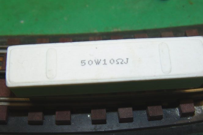
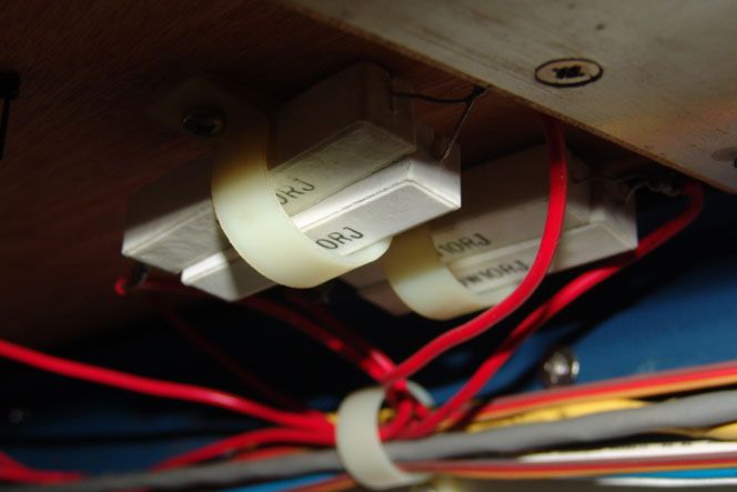
My very simple solution, which has worked for years, was to install two 50W 10 ohm resisters in parallel across all block breaks. This way the dead block now becomes a low voltage block, receiving some voltage from the the two adjoining hot blocks.  This  slows the fast train enough to maintain safe spacing.


Once and a while a light draw fast train will sneak through the low speed block early and catch up with the slow train. One block has extra voltage drop, almost stopping any train, which usually allows safe spacing to be re-established.  Rarely I have had to change a train to better match train speeds. Roller hop is now a barely noticeable blinking. This low voltage collision control system will work equally well regardless of the train direction. However, reverse operation will require modified block controls.


I know it sounds too simple to work - but it does.  Note in the two videos, below, the fast train is slowing, waiting for the the green lights.  Also in one video, toward the middle, my D&H Anniversary T1 is poking along on the adjacent track in a slow block.  When when the slow train leaves the block ahead full voltage returns, the head light gets brighter and the train resumes full speed.


Dale H is right, a short in the slow block will mean high current through the resistors which will heat up or blow. Always use fast blow breakers, like those in Z 4000's. Do not use old ZW's with this system. Alternately use fast blow fuses in fuse holders.

Last edited by zhyachts

My Grandfather used the ceramic resistors to drop voltage behind the train in the 70's with ZW's, but there was only conventional locos back then.  He used 8 blocks on each of the 15 x 30 passenger loops (2). Mostly two a-b-b-a war bonnets, and double & triple headed Lacky teams.  The only big issue was too fast a start up on some once power returned to full. But he slowed that eventually too, I forget how. The cars eventually got caps for the lights too I think.

  I don't remember any fuses, but they may have been under the control stations lid. I still have a half dozen extra ceramic resistors in a parts drawer.

Originally Posted by Adriatic:

My Grandfather used the ceramic resistors to drop voltage behind the train in the 70's with ZW's, but there was only conventional locos back then.  He used 8 blocks on each of the 15 x 30 passenger loops (2). Mostly two a-b-b-a war bonnets, and double & triple headed Lacky teams.  The only big issue was too fast a start up on some once power returned to full. But he slowed that eventually too, I forget how. The cars eventually got caps for the lights too I think.

  I don't remember any fuses, but they may have been under the control stations lid. I still have a half dozen extra ceramic resistors in a parts drawer.

Adriatic


I may be wrong, but isn't block control for trains operating in conventional mode?  With speed control blocks should not be needed for collision avoidance.  i only operate in conventional mode.

Originally Posted by zhyachts:


The block signals can be circuited the same way as previously described. You may have to change the block numbers a bit to accommodate the new drawing. Discard the previous diagram for block power distribution. Roller jumping must addressed as described. If it is not,you will have erratic operation if using the diode dropper and risk transformer damage if using more than one ZW tap to the same loop. You should not connect A and B for example (which can be done with rollers) if set at different voltages.


Sorry this is so involved but I do not see an easier way. I think I drew it correctly but check it out. If others have ideas feel free to present them.


Dale H


I have two "presentation loops", one CW, one CCW, each 170 feet long with 6 relay controlled blocks.  The theory is a dead block follows the slower train and the faster train would enter it and stop. When the slower train exited the nearest hot block the dead block would be re-energized.


Several problems.  First, particularly with worm gear drives, the engine would come to a very unrealistic crash stop and a traction tire ripping jump start.  Second, roller hop (current passing from the back of a passenger car to the front re-energizing the dead track) would result in lots of jerky running. Third, on some traditional E units the engine would shift to neural and not restart.


My very simple solution, which has worked for years, was to install two 50W 10 ohm resisters in parallel across all block breaks. This way the dead block now becomes a low voltage block, receiving some voltage from the the two adjoining hot blocks.  This  slows the fast train enough to maintain safe spacing.


Once and a while a light draw fast train will sneak through the low speed block early and catch up with the slow train. One block has extra voltage drop, almost stopping any train, which usually allows safe spacing to be re-established.  Rarely I have had to change a train to better match train speeds. Roller hop is now a barely noticeable blinking. This low voltage collision control system will work equally well regardless of the train direction. However, reverse operation will require modified block controls.


I know it sounds too simple to work - but it does.  Note in the two videos, below, the fast train is slowing, waiting for the the green lights.  Also in one video, toward the middle, my D&H Anniversary T1 is poking along on the adjacent track in a slow block.  When when the slow train leaves the block ahead full voltage returns, the head light gets brighter and the train resumes full speed.


Dale H is right, a short in the slow block will mean high current through the resistors which will heat up or blow. Always use fast blow breakers, like those in Z 4000's. Do not use old ZW's with this system. Alternately use fast blow fuses in fuse holders.

If you use resistors you could put a 1 amp polyfuse in series. That would protect it from shorts and burning up.


As in examples I related in earlier posts,the resistor is not protected by the transformer breaker,regardless of breaker speed in some cases. For example a 2 ohm resistor at 15 volts would allow 7.5 amps of current flow if the track was shorted. Not enough to trip the breaker of a ZW but would allow over 100 watts of heat in the resistor circuit. The 10 ohm fixed one is pretty safe if mounted correctly to allow heat to shed about 40 watts at 20 volts. The 2 10 ohm ones in parallel make a 5 ohm 100 watt resistor and would have to shed up to 80 watts in a short. They need air space around them or they could cause a fire if around combustibles.


Still I think diodes offer a better solution for the reasons stated. Relays allow for the use of timers and train routing.


Dale H


Last edited by Dale H
Originally Posted by zhyachts:
Originally Posted by Adriatic:

My Grandfather used the ceramic resistors to drop voltage behind the train in the 70's with ZW's, but there was only conventional locos back then.  He used 8 blocks on each of the 15 x 30 passenger loops (2). Mostly two a-b-b-a war bonnets, and double & triple headed Lacky teams.  The only big issue was too fast a start up on some once power returned to full. But he slowed that eventually too, I forget how. The cars eventually got caps for the lights too I think.

  I don't remember any fuses, but they may have been under the control stations lid. I still have a half dozen extra ceramic resistors in a parts drawer.

Adriatic


I may be wrong, but isn't block control for trains operating in conventional mode?  With speed control blocks should not be needed for collision avoidance.  i only operate in conventional mode.

It wasn't meant to be personal Bill.  

Only my experience with a layout I grew up around.

 One that sounded like quite similar in a way.

 I should back you. A fuse is seldom a bad idea.

 I just don't remember any.


 I am being made to think, and change my normal "circuit use" thoughts, to working with a much larger canvas.  So, I am learning.

Learning what was likely done under our layout once, from just reading this.

  Thank you. 


 I assumed the jack-rabbiting was use of relays.

I'd seen the resistors, but had never given anything other than fleeting thought to the theory of their uses, or looked up the part numbers on them to know for sure what they are.

  I had assumed for the moment, the extra numbers might be important. I guessed they were the thermal fix for the jack-rabbiting. A thermal resistor that dropped resistance with temp.

 Now, I question my original "quick theory" greatly.


  The old one, with all powered units, long trains, 8 "sections", approx. 15x30 rounded box Gar Graves. It used ZWs. I don't remember fuses.

  I do remember banks, as is 9+ of those (hot..ouch) ceramic resistors on the underside, in 8 spots. With up to six motors on a section, yes, banks of them.


  I only run conventional too.

I don't know why I mentioned no command.

An unconsciously made disclaimer to anything I might ad?

To nip at the bud a "Change to command" post that may follow?

 Conversation filler? 

Anyhow, again not personal

Now this is.....

 My favorite "speed control" is four blocks, 2 grades, E-33, & a prewar Z

  Being "loopy" and 1/3 the size of the old layout, I keep it to one train per line.

With a drawer of resistors, I'm now getting urges for use elsewhere.


 Ok...The E-33 is tmcc, but I don't own a system.  


Add Reply

Post
×
×
×
×
Link copied to your clipboard.
×
×