I'm converting some K-line passenger sets with Streamlighting to LED strips. For the main lighting, I use a circuit with a rectifier, 470uF cap, and CL2N3 constant-current driver.

The problem I'm having is how to deal with the marker lights in the observation cars. The K-line system used diodes in series with the main lighting to get a 1.5 volt tap:


I can't put the diodes in series with the CL2N3, because 20mA is not enough to light the bulbs. (I think they take about 90mA at 1.5 V).
But if I just put the diodes across the track power that's almost a short circuit. I could put resistance in series with the diodes, but that generates lots of heat.

I suppose I could try one of the Supertex 100mA drivers, but is there a simple way to give the rear lights a 1.5V supply?
Original Post

Replies sorted oldest to newest

I don't recommend using a constant-current IC to drive 3 parallel bulbs. If one bulb goes out, its current will be forced into the other 2 bulbs. Instead I suggest a constant-voltage solution like the diode method you show. If one bulb goes out, the remaining bulbs are not affected.

Is it possible/practical to re-wire the 3 marker bulbs in series? This would give you a 4.5V load requiring 30mA rather than a 1.5V load requiring 90mA.

But assuming the objective is 1.5V, this thread shows a circuit which generates 3V DC to illuminate some bulbs. A parts list is given to give you an idea of parts cost. By simply altering the resistor values this circuit can generate 1.5V instead and easily handle 90mA. Since you already have a rectifier and capacitor for your LEDs, it may be that all you need are the LM317T and two resistors - sort of like the 4.5V add-on circuit shown later in the thread. If this approach is something you'd like to pursue, we can get into the specifics.

BTW, the LM317 with a single extra resistor can perform the function of a CL2N3. While you can't beat the convenience of a single chip that generates 20mA with no additional fuss, if you're assembling a bunch of parts anyway, the LM317+resistor approach can lower cost. The resistor value sets the current level so you aren't limited to 20mA. The LM317 is more widely available than the CL2N3.
Nothing wrong with the resistor method. Plus RS charges a pretty penny for the LM317. I pay less than 25 cents each in small qty mail-order but there’s shipping. And if you punch in LM317T on eBay you get hundreds of hits at similar prices though you’ll wait to get them from Asia.

You might need to game the system so to speak - so suppose you decide on 200-ohm, 2-Watt resistor. If RS doesn’t sell that, you can use 2x 100-ohm 1-Watt in series, or 4x 50-ohm (i.e., 47 ohm) ½-Watt in series, etc. I see, for example, RS sell 5-packs of ½-Watt resistors for $1.19. This has the advantage of spreading the heat if you have the space. I hope I’m not insulting you by pointing this out

A comment about the resistor method. A regulator IC such as the LM317 will generate a relatively precise voltage vs. just the resistor. There’s a rule of thumb with house lightbulbs that (IIRC) a 5% increase/decrease in the operating voltage will halve/double the life of a lightbulb – in other words a dramatic effect. I don’t know if this is relevant to the tiny bulbs in model trains but I’d err on choosing a slightly larger resistor than what the equations pop out.

Indeed – whether LM317 or resistor, it’s a win all around if you can conveniently re-wire the lights to a series configuration.

But if you still want to make RS shareholders happy, or just want to explore the LM317 method in more detail, we can do that too. If so please elaborate on your LED circuit so as to determine how best to tap in.
Well, the advantage of RS is that I can get it this afternoon if I want! Of course for quantity I would do Mouser etc.


But this is turning into a more difficult problem. It turns out the drumhead bulb is not the same as the side marker bulbs. The side markers measure at 4.4 ohms, while the drumhead is 3.2 ohms. So in series the drumhead is too dim.

The markers might be replaced with LEDs too, but the drumhead would be quite hard to replace.

I'm getting stumped. The bulbs draw much more than the 90mA I thought - more like 170 mA - so I would be dissipating about 4 watts if I regulate track voltage down to 1.5v.
A technical note:
Putting a resistor in series with an incandescent bulb isn't a good idea. As the filament ages, it loses metal, especially at any crystalline imperfections in the filament. As a result, the resistance of the filament goes up, and this results in an increase in voltage across the bulb. (Higher resistance compared to the dropping resistor results in a higher percentage of voltage compared to the dropping resistor.) This makes the filament get even hotter, especially in the eroded areas, and the aging is accelerated.

A constant-voltage source will avoid this problem. The power in the lamp will go down as the filament ages and rises in resistance.
So the thick plottens…

Are your LED strips the 3-LED sections discussed on the passenger car lighting threads? If so, here’s an approach. Use a generic 7812 voltage regulator IC, which puts out regulated 12 Volts such as RS #276-1771 @ $1.99 or, say, DigiKey MC7812CTGOS-ND @ $0.53. These can then directly drive your LED strips with no CL2N3 required as the strips drive the LEDs at ~20mA if you supply it 12V.

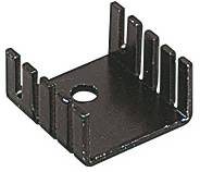
Then, also power the LM317T from this 12V. Even at 170mA, a LM317T set to 1.5V would drop 10.5V and dissipate roughly 1.8 Watts which is manageable for the so-called TO-220 package. But I’d use a heatsink.

Yes, the 12V regulator handles all the current – LEDs and incandescent. I don’t know how many 20mA strips you have but let’s say 4 strips so adding them to the 170mA incandescent current totals 250 mA. Starting from 18V DC (yes, probably a bit less from AC-DC diode drop), the 12V regulator drops 6V dissipating 1.5 Watts which as before is manageable for the TO-220 package though even at 1.5 Watts I’d still use a heatsink.

As an aside, both the 7812 and LM317 ICs have so-called TO-220 full-pack variants where the package tab is not metal so the mounting hole is insulated from the 3 electrical pins. This allows you to mount the IC directly to the car’s under-chassis frame (outer AC rail) to get a free and more than ample heatsink. The insulated packages (usually called TO-220F or TO-220FP) are typically a bit more expensive and not something you’ll find at RS (I don’t think anyway).

There are many approaches that would work so even if you aren’t using the 12V LED strips this simply illustrates how to manage the heat by spreading it around while still using low-cost generic components.

Of course if converting to LEDs is a possibility for any of the marker incandescents that’s another story…
I find the 3-LED units to be too bright for a passenger car interior at 20 mA. I am using a 3' strip of those LEDs with each trio running on 12V to light the interior of my full-size Ford van!

I find 20 mA shared by a strip the length of the passenger car to be about right for me. The reels are inexpensive enough to allow this "extravagance" and get good uniform lighting.
Yes, I'm using the 3-LED strips. Like Dale I find that running a car-length strip @ 20mA total is a pleasing brightness.

I think I am going to bite the bullet and replace the marker lights with some 3mm white LEDs. That way I should be able to wire them in series with the strip, or off another CL2N3 if necessary. Rewiring the drumhead is going to be a pain but ultimately easier than installing multiple heatsinks.

Thanks for the help guys - I'll report back when I install them.
I think gunrunnerjohn means the average voltage seen by the regulator(?). By sizing the cap appropriately, during the off half-cycle it discharges to, say, 3V but the regulator will always be on delivering continuous 1.5V to the lamps. In any event, definite power savings.

To your point, if the voltage regulator is happy with half-wave DC, eliminate the cap and set the output to 2.1V (instead of 1.5V). Since filament power is proportional to voltage-squared, driving the lamps half the time at 2.1V will be the same brightness as all the time at 1.5V. Even more power savings. Adjusting up the regulator simply compensates for the old hat trick of reducing filament brightness by half-waving - and no undue flicker (separate from fast responding LEDs). That is, filament flicker from contact noise is a separate issue (i.e. clean your track, wheels, rollers).

Carrying this line of thinking, one option is to only let the cap charge to, say, 6V by chopping the rectified AC. In other words some crude version of a switching supply. The incremental component cost would be modest (under $1) but the extra assembly hassle dooms it as a DIY project.

But really, all this blather goes poof by converting the markers to LEDs!
John, I think you have a basic conflict here. If you have enough capacitor to smooth out the power gaps due to dirty track, you are talking about at least a tenth of a second hold time. A half cycle of power is only 8.3 milliseconds, which means a capacitor sized to flywheel through dirty track is going to charge to full peak voltage.

Maybe you could add a resistor on the charging side, but that would slow down the recovery after a power gap.
Don't know how far along you got with LEDs, but if you are staying with lamps, I found these on eBay for as little as $2 w/free shipping from Asia. Search on "LM2596 module" and there are dozens of sellers and variants.


These are compact DC-in, DC-out switching regulator modules with no heat issues vs. LM317T method. You'd just adjust the output to 1.5V using the trimpot. A 470uF cap after your existing input diode ought to power the 3 lamps for some 0.1 sec for flicker reduction if you need that. I have no experience with these but it's quite a value.
Well I just installed the LED markers. There wasn't quite enough voltage to drive three white LEDs in series with the strip, so I just powered them from a separate CL2N3. Looks pretty good - though those white ones are pretty bright at 20mA.

But dang - $2.00 for an adjustable switcher. That could come in handy, as long as it didn't inject noise into the track supply that would interfere with DCS or TMCC.
quote:
Originally posted by Professor Chaos:

But dang - $2.00 for an adjustable switcher. That could come in handy, as long as it didn't inject noise into the track supply that would interfere with DCS or TMCC.


Indeed - I couldn't resist so I ordered one and it came in less than a week from Hong Kong - exactly as pictured. As a test case I set it for your original load of 1.5V @ 200 mA with 16V DC input. So rather than a LM317-type linear efficiency of less than 10% (1.5/16), it ran at about 50% (only 40 mA input). And no heatsink needed as dissipated heat drops from ~3 Watts to ~1/3 Watt.

To your point, the input noise is rather "exciting" as viewed on a scope so it's left to the student to gauge feasability for command systems.

I figure these will be nice for localized regulation of low-voltage layout accessories, or to add regulation to unregulated wall-warts.
Post

OGR Publishing, Inc., 1310 Eastside Centre Ct, Ste 6, Mountain Home, AR 72653
800-980-OGRR (6477)
www.ogaugerr.com

×
×
×
×
Link copied to your clipboard.
×
×