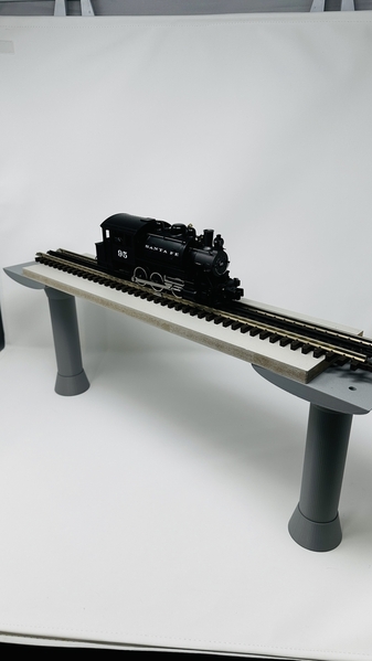
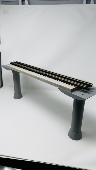
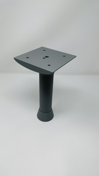
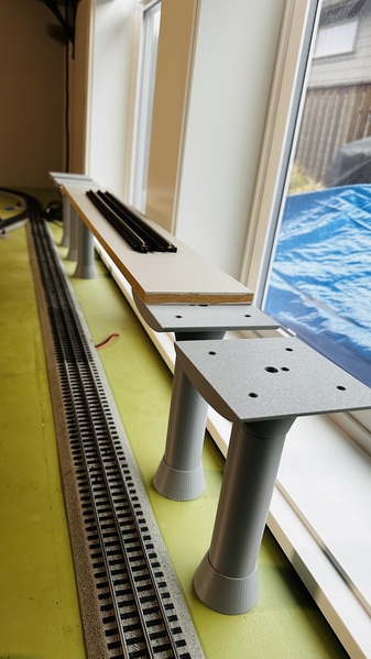
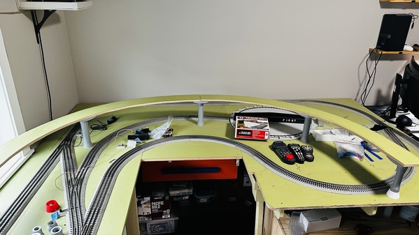
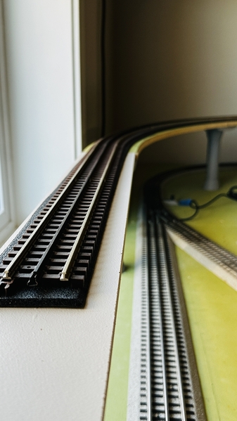
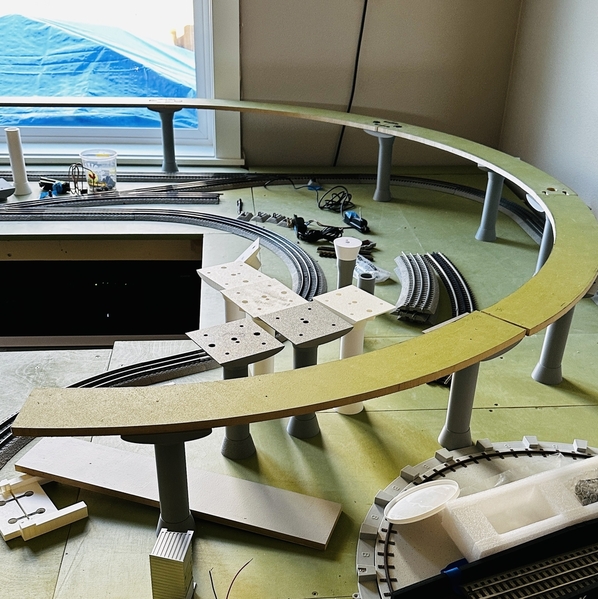
The objective of this project was to learn more about 3D design and printing, and to create an elevated single loop of track for my layout.

Of course like most model railroading projects itʻs still in progress!

Iʻve been planning to add a second level for some time, and really would have liked double track, but my layout is small (85 sq ft) and built so 90% is no more than 18" from the layout edge.  Because my ground level track is already installed, I wanted supports that use minimal space and are flexible to position.

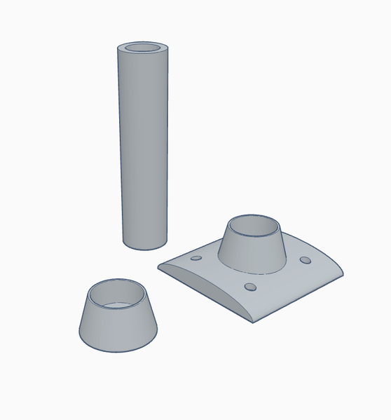
This project was designed by me using Tinkercad and itʻs basic shapes library.  It took at least 40 hours starting at 0% knowledge of the software.  Printing was done mostly on my Bambu P1P printer, using PLA filament.  Many test prints were made to adjust fitment and esthetics.   Tinkercad is great and there is much more to learn about it, however I am planning to try Fusion 360 for my next major project.

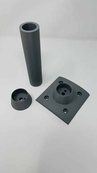
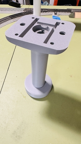
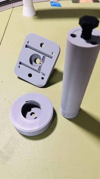
The viaduct pillars are inspired by the Honolulu Rail Transit Project support pillars, I have included a photo that I took during early construction in 2015.  While I love the look of wooden trestles, steel girders and steel beams, I wanted the modern look of concrete.  Which has the advantage of easier placement and physical access.  The ground to top of track height is 9", with 8" underneath.  The design of the pillar as a separate printed column allows the height to be adjusted.

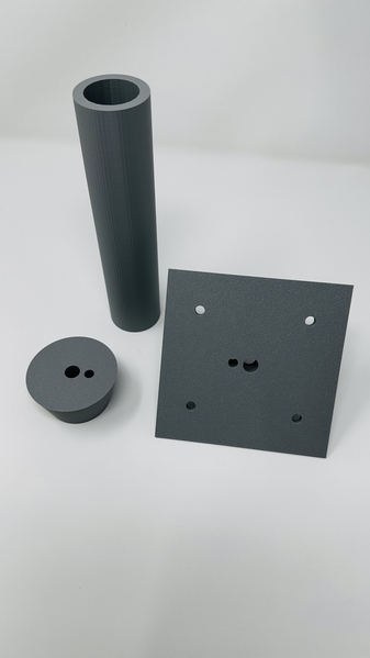
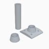
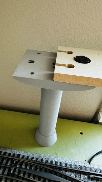
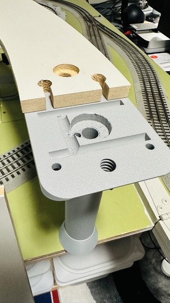
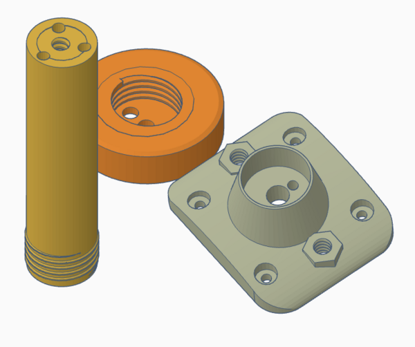
The lower viaduct base is designed with 2 holes, one for attaching to the layout base using a lag screw, and a smaller hole for wiring if required.  My layout is smooth finish 3/4" plywood. The upper viaduct base has 4 holes for attaching the wood MDF track bed from underneath.   It also has 2 holes left over in the center section, because itʻs the lower base flipped over and grouped.

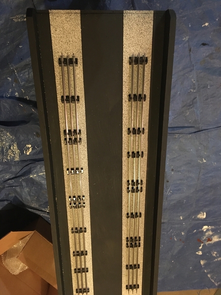
The track bed is 1/2" MDF painted grey.  I like MDF because itʻs smooth, easy to machine, and cheap.  I have a small concern about sagging over longer spans but will "cross that bridge when I get there". 

I will be working on the curved sections this week and hope to install at least 25% of the loop.  I am using Atlas track and foam roadbed with O72 curves.  Will update this post then with new progress.  Suggestions and comments welcome!

Photo of Honolulu light rail pillars, taken by me in December 2015.
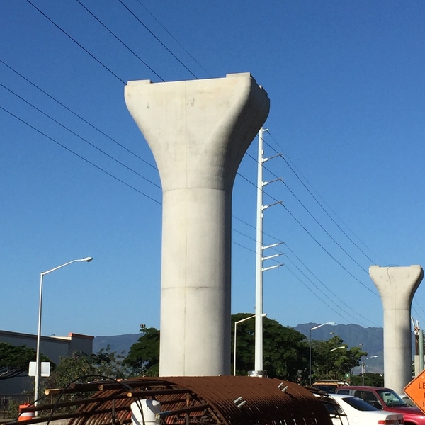
Honolulu Light Rail Pillar 1

Printed Model Railroad Viaduct:
IMG_9233IMG_9234IMG_9239

IMG_9238IMG_9236IMG_9240Rail Viaduct 3 components

Attachments

Images (8)
  • Honolulu Light Rail Pillar 1
  • IMG_9233
  • IMG_9234
  • IMG_9239
  • IMG_9238
  • IMG_9236
  • Rail Viaduct 3 components
  • IMG_9240
Last edited by Kelunaboy
Original Post

Replies sorted oldest to newest

Thanks for the feedback!

Your suggestions for a more "concrete" looking finish are well received, PLA filament does look very plastic.   Using a texture spray paint like Rustoleum Desert Bisque would work very well.  However there are a few other things I will to try first.  
For experienced 3D printers the using the "fuzzy" and "seam" printing options are well known - but it was new to me.

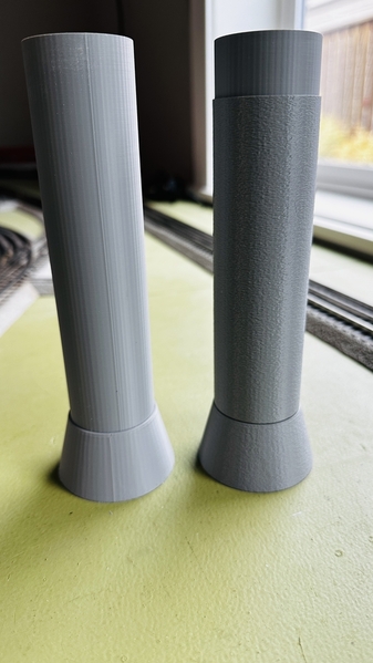
So I tried it on a few pieces and to me itʻs an improvement,.  In the first photo, the original is on the left, and on the right shows the "fuzzy" and "random seam" settings.

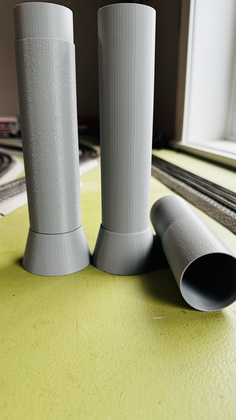
The next photo shows the sleeve I printed with the texture that slips over the existing column, rather than re-printing the entire column.  The "sleeve" printed upright without any problem and slipped over with a snug fit.  It also widens the column for a more fitted look.

IMG_9245IMG_9243

This photo shows a test placement of the O72 curve using the 9" tall supports.

IMG_9241

I will be designing guard rails to keep derailments from falling off the upper level, something low profile using the same smooth concrete theme.
Waiting on more filament to arrive and experimenting with PETG filament, which promises a smoother finish, faster printing, and more flexibility.

Attachments

Images (3)
  • IMG_9245
  • IMG_9243
  • IMG_9241

L(.)(.)king GOOD!  That's some VERY NICE WORK!

I primarily print with PETG.  Good Layer Adhesion and Smooth Prints will require you to Slow the Print Speed  Down to around 60%-75% of full speed.  For the Best Layer Adhesion and Print Smoothness Turn the Cooling Fans Off.  Other settings/adjustments (too numerous to list here) can also improve PETG prints.

It looks like you are using 64 sided cylinders... I almost always use the 'perfect circle' for cylinders and bores (holes) ...smooths things out a bit.

Attachments

Last edited by Dennis-LaRock

I usually end up making my own designs rather than copying... and, it's a lot faster for me to knock out a prototype in TinkerCad than in 360.  I will export/import the design into 360 for mesh fixes and contouring.  You can do an awful lot in TinkerCad.

For exact copies of items you can use a high quality raster image (.jpg, .png etc.) and convert them into vector images in Illustrator or Corel Draw.  Import those vectors into 360, Rhino or the like for sizing, mesh fixes and contouring etc.

Whoops!  Almost forgot... the Perfect Circle is what I use to make TPU (Shore 83A-85A) Traction Tires.

Last edited by Dennis-LaRock

Update 8/31/24

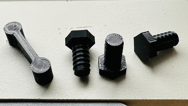
Slow progress and getting side tracked along the way.  Modifications designed for top down assembly, avoiding reaching under the rail.  Using soft flexible connectors printed with TPU 95A filament.  I need more practice with this, my prints are not consistently firm and too much stringing.

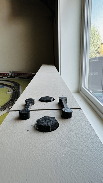
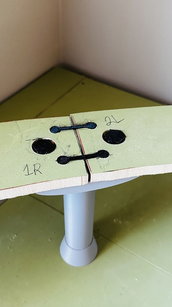
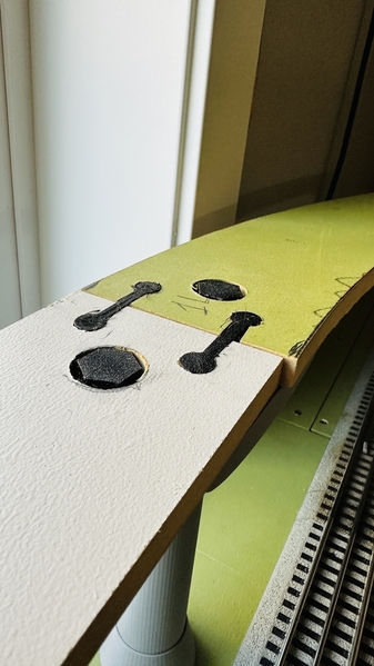
Still using 1/2" MDF but added keyhole like slots to each adjoining side and using flush TPU keys to hold the sides together.  Also added a soft TPU bolt to fasten the MDF down to the top of the pier.  The goal was easy working access from the top side.  MDF flexing is a problem and I will need a support every 10" or about every section of track.  I like the thinness of 1/2" thick roadbed so I donʻt think moving to 3/4" plywood would retain the look Iʻm after, and plywood is not as easy to "machine".   Going to stick with MDF until I get trains running.

IMG_9260IMG_9261IMG_9262IMG_9263IMG_9264IMG_9266

Attachments

Images (6)
  • IMG_9260
  • IMG_9261
  • IMG_9262
  • IMG_9263
  • IMG_9264
  • IMG_9266

Update 9/12/24 - putting this project on vacation hold for 3 weeks while we take a Mediterranean cruise next week.  I am taking my laptop loaded with Autodesk Fusion - hoping for some time during the sea days to learn it.  I did spend a day tying out FreeCAD last week, but it did not work well for me on Mac OS.

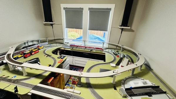
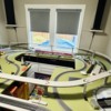
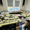
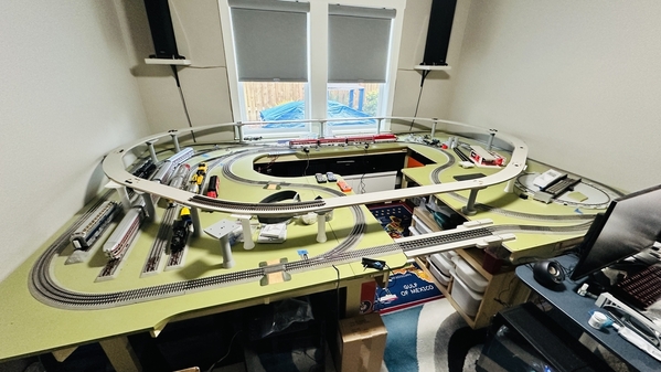
Hereʻs an overview of my upper O72 loop that will use Atlas sectional track, this may not be the final track layout.  Iʻm pleased with how quickly I can try different options, itʻs like a "sectional" roadbed.

Layout 9-11-24 right overviewLayout 9-11-24 left overview

I have improved my printing with TPU-95, which Iʻm using for flexible roadbed joiners and hold-down bolts.  Smaller batches printed at 50% speed works best for me.  

Version 2 of my "roadbed system" has wiring channels added to the top pier for power drops.  These are hidden under the MDF roadbed.

Other changes include a hold-down bolt with recess attaching the top pier to the column, and threaded column base mating to threaded base pier.

My goal for switching to Fusion from Tinkercad is making revisions easier and faster.  I expect to revise everything to be more "prototypical".

I am making the MDF roadbed using traditional woodworking power tools, however I am planning designs using a CNC Router.

Thanks for looking!


IMG_9273IMG_9274

IMG_9275IMG_9276Screenshot 2024-09-11 at 8.59.10 PM

Attachments

Images (7)
  • IMG_9273
  • IMG_9274
  • Layout 9-11-24 right overview
  • Layout 9-11-24 left overview
  • IMG_9275
  • IMG_9276
  • Screenshot 2024-09-11 at 8.59.10 PM

Add Reply

Post

OGR Publishing, Inc., 1310 Eastside Centre Ct, Ste 6, Mountain Home, AR 72653
800-980-OGRR (6477)
www.ogaugerr.com

×
×
×
×
Link copied to your clipboard.
×
×