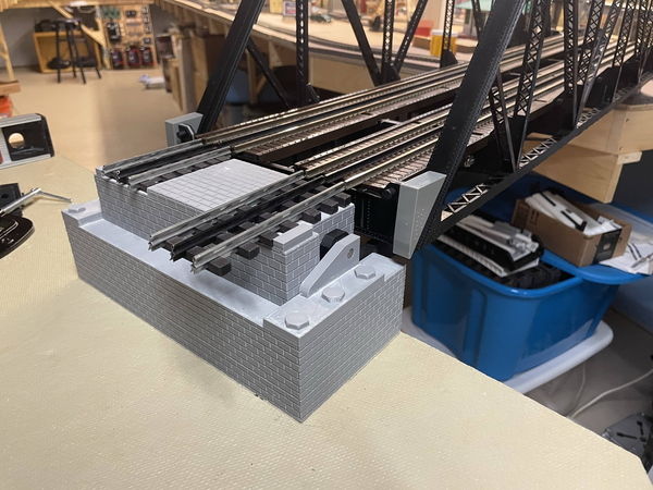
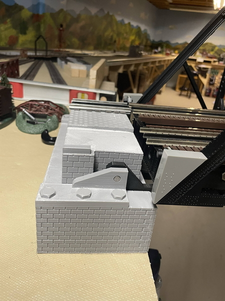
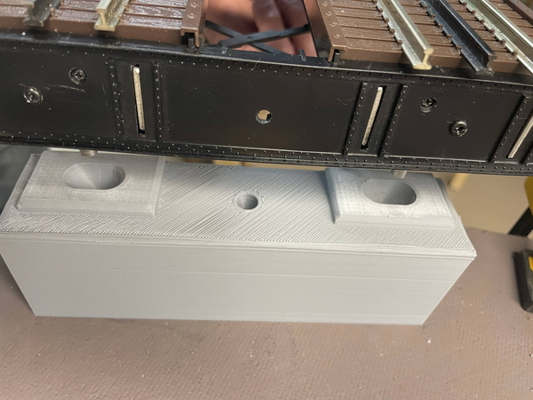
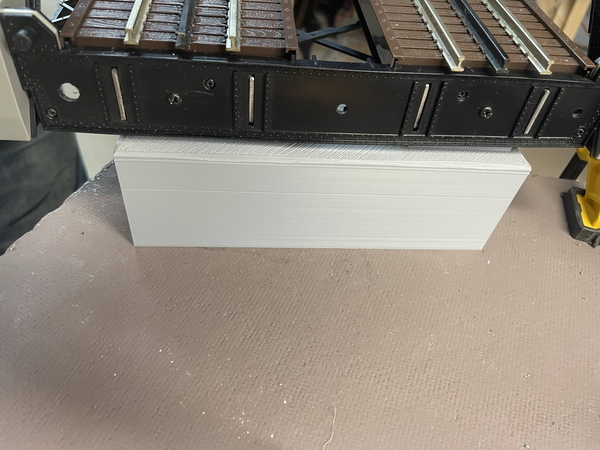
Sorry for being absent, been working on the lift bridge mounting base. The more I think I know in fusion360, the humbler it makes me. I have a quasi-parametric design for the hinge base of the bridge. It will put the track height at 4 inches. I wanted it to scale height wise and also allow different size "bricks" to make the walls. I'm happy with the look, and it appears I can change the height without breaking the design. However the brick work still needs some revising. I started the print, which will take 2 days and 22 hours to finish! OMG! So here is a fusion "pic" of what is printing as I am typing this post. I'll work on a couple of faux bolts to use as screw caps for the six mounting holes that are countersink for mounting the base to the table. I have at least until Sat. before the printer is free to print again... lol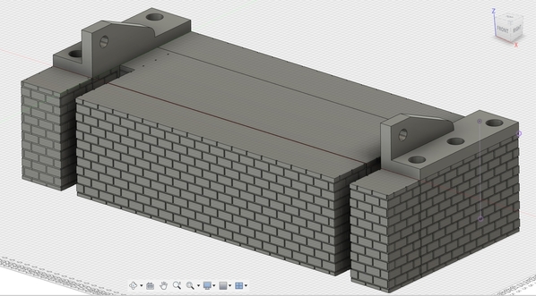
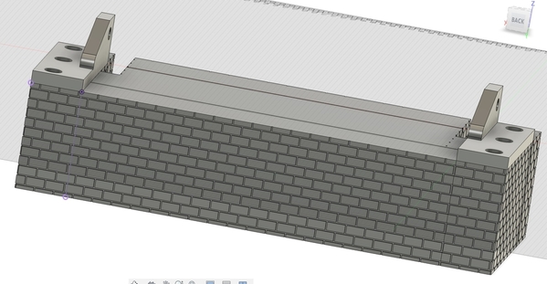
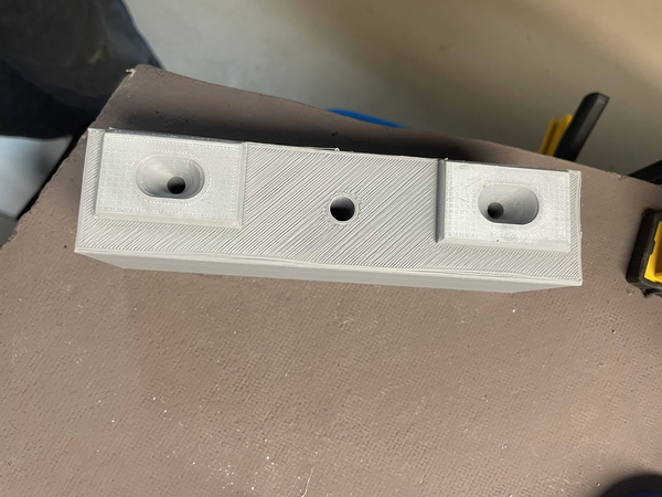
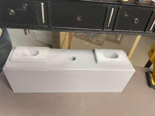
Update - Have finished printing out and testing the hinge support for the lift bridge. Works well and now the task of cutting track rails at proper angle to allow bridge rails and track rails to have as small a gap as is possible. Also have printed and checked the landing pad of the bridge with guide pins. That also aligns well and I am awaiting the track support for that side of bridge to finish printing. (two day 6 hour print time) In the landing/alignment pin area, I have used stainless steel pins and allowed for a spring to be put in alignment pin receptacles allowing them to be wired, to be used as an electronic flag that the bridge is in place or not. Not sure what I'll do just yet but that is down the road.
Now to figure if I use cookie cutter and raise rail elevations or some other supports. If cutting the plywood/homosote base is the preferred direction, then the width of the road bed needs to be determined, and do I use both the plywood and homosote on the grade? All suggestions are always appreciated. Thanks in advance. john
Attachments
John, I'm glad the lift bridge hinge supports, etc are working out well. I see that I read your last post, but forgot to comment that the support drawings look great! My brain hasn't been working well lately. I think I have a screw loose. ![]()
I used plywood and Homasote on the grades and throughout except for a couple places I miscalculated and didn't have room to match the track heights up. There I tapered the Homasote (not fun) to match up and I have one 2-foot stretch where it was easier to lay the track right on the plywood. I'm not saying what I did was best, just saying that's what I did. ![]()
@Mark Boyce posted:John, I'm glad the lift bridge hinge supports, etc are working out well. I see that I read your last post, but forgot to comment that the support drawings look great! My brain hasn't been working well lately. I think I have a screw loose.
I used plywood and Homasote on the grades and throughout except for a couple places I miscalculated and didn't have room to match the track heights up. There I tapered the Homasote (not fun) to match up and I have one 2-foot stretch where it was easier to lay the track right on the plywood. I'm not saying what I did was best, just saying that's what I did.
Good to know you used both where possible and adapting where needed. I can't imagine the snow storm that ensued tapering Homosote! wow wam! what a mess!
John, I’m still trying to recover! 😄
John, those sure look great, I am glad to hear things are moving along in the right direction. I am wondering where did you order or buy the brass pins and receivers for them?
@Richie C. posted:Not over a river, but I used some pre-wired 12-18 volt (ac and dc compatible) led strips that I glued in place under a bridge to illuminate a hobo camp underneath. They already have the correct resistors on the strips. I ran the wires through the bridge piers to under the layout in order to hide them from view. Being 18acv compatible, you can connect them directly to track power, if needed.
You should be able to find some on the 'bay in a light range that is not too bright. If they turn out too bright after you get them, you can always paint the lights with Tamiya Clear Orange, which will tone them down substantially.
Your backdrop looks wonderful! You did a great job with it. If you're running wires for LED Lights with the resistor and they happen to have a red wire, you can hide your wires by running them through black heat shrink tubing and attaching them to other material with either black silicone sealer, hot glue, or for more permanent drops of super glue. I prefer the black silicone sealer as it's easily removable in the future. You can find rolls of the heat shrink tubing on the Bay, A**zon, or other foreign sites like Ali Express for example, cheaply in all kind of sizes.
@mike g. posted:John, those sure look great, I am glad to hear things are moving along in the right direction. I am wondering where did you order or buy the brass pins and receivers for them?
Thanks Mike,
It may look great, however functionality fails. ![]() I ran into an issue which I am hoping to resolve by tomorrow. When the bridge lifts on the pinned side there is too much interference between stationary track and bridge track. Going over notes from you and others, I have the suspicion the oversized gap between tracks is from not listening/reading/adhering to the note of having hinge point located above the track. I am reprinting the piviot base and support arms to have the pivot point above the rails so that clearances will be minimal. So it takes three days to print the base and 5 hours for each support arm. Just finishing up the base as I type and will print the arms, hopefully today. The alignment pins are steel 1/4-28 which I believe I got a while ago. I hope it is ok to post a link, if not I apologize and will remove. "https://www.amazon.com/gp/product/B00EB1TQ2W/ref=ppx_yo_dt_b_search_asin_title?ie=UTF8&psc=1" They do not have any from this seller, however if you need some I ordered 5 thinking I would get 5 and not 5 bags of 5 lol so pm me if you want some. The hinge pins I had laying around for decades. I am a pack rat for sure. The receiver is the base I 3d printed. I hope I understood your question.
I ran into an issue which I am hoping to resolve by tomorrow. When the bridge lifts on the pinned side there is too much interference between stationary track and bridge track. Going over notes from you and others, I have the suspicion the oversized gap between tracks is from not listening/reading/adhering to the note of having hinge point located above the track. I am reprinting the piviot base and support arms to have the pivot point above the rails so that clearances will be minimal. So it takes three days to print the base and 5 hours for each support arm. Just finishing up the base as I type and will print the arms, hopefully today. The alignment pins are steel 1/4-28 which I believe I got a while ago. I hope it is ok to post a link, if not I apologize and will remove. "https://www.amazon.com/gp/product/B00EB1TQ2W/ref=ppx_yo_dt_b_search_asin_title?ie=UTF8&psc=1" They do not have any from this seller, however if you need some I ordered 5 thinking I would get 5 and not 5 bags of 5 lol so pm me if you want some. The hinge pins I had laying around for decades. I am a pack rat for sure. The receiver is the base I 3d printed. I hope I understood your question.
Again thanks
@Gary P posted:Your backdrop looks wonderful! You did a great job with it. If you're running wires for LED Lights with the resistor and they happen to have a red wire, you can hide your wires by running them through black heat shrink tubing and attaching them to other material with either black silicone sealer, hot glue, or for more permanent drops of super glue. I prefer the black silicone sealer as it's easily removable in the future. You can find rolls of the heat shrink tubing on the Bay, A**zon, or other foreign sites like Ali Express for example, cheaply in all kind of sizes.
Thanks, I did the best I could as I was learning as I was going, so to speak. Thanks for the great idea on hiding the red wires! Also I seldom think of silicone sealer for gluing, so I will now keep that in mind. For me it is always better to have things semi-permanent to correct my mistakes without making things worse because they are fused together. ![]()
John, yes if the hinges either aren't raised or you use special offset hinges, the rails will bind unless you have a sizable gap, which isn't good for running trains either.
Talk about fusing things together permanently; I have been gluing less and less as time goes on. Almost everything on my layout is fastened together with screws and no glue because I can't be trusted to do it right even after measuring a dozen times. I used to think one of my strong points was attention to detail, but unless I have been kidding myself all along, that skill is diminishing as of late! ![]()
@Mark Boyce posted:John, yes if the hinges either aren't raised or you use special offset hinges, the rails will bind unless you have a sizable gap, which isn't good for running trains either.
Talk about fusing things together permanently; I have been gluing less and less as time goes on. Almost everything on my layout is fastened together with screws and no glue because I can't be trusted to do it right even after measuring a dozen times. I used to think one of my strong points was attention to detail, but unless I have been kidding myself all along, that skill is diminishing as of late!
Yes, I resemble your remarks on missing details more often than I ever did while working. ![]()
Hi John, I tried the link you provided, and it just took me to Amazon. Are you able to connect wires to them for power to the bridge? I really love the way the bulkheads look, I sure hope you get it figured out!
@mike g. posted:Hi John, I tried the link you provided, and it just took me to Amazon. Are you able to connect wires to them for power to the bridge? I really love the way the bulkheads look, I sure hope you get it figured out!
Sorry about the link, they seem to no longer be offered for sale. I snap shot the description to help you find them on the net. I plan on using the wires to these pins just as an indication of down position. I would think there could be too many sparks if track power were run through them, plus they are steel, so not the best conductors. They will be controlling a relay that will handle the power.
Attachments
Well, I thought the lift bridge project was almost finished... A thought crept into my last remaining brain cell, to check clearances... I needed to have that thought before I began the hinge assy etc. Needless to say, I took the pretty shiny unused NMRA gauge and the hinges will impede any train car, engine or caboose you could imagine. So back to the drawing board. So the two items that SHOULD have been at the top of the design list (track clearance and train clearance) were ignored, not thought of, live and learn. Only good news is the bridge landing is good to go! New hinge plates to secure to bridge have been redesigned and one is currently printing. I'll get the other tonight completed and will mount and redesign stationary hinge and track supports. I'll have to constantly check clearances as I go laying track. It looks ok on scarm, however I need to touch and feel the layout for self reassurance.
It’s always something!! 😑
I was the designer and coordinator of the building process for the modular O-gauge layout of CAMRC (Central Arkansas Model Railroad Club) based in Conway AR. We installed a dual-track MTH Lift Bridge across an intentional gap between two modules for aligning them with the bridge during set-up for trouble-free operation (including a circuit designed by a club member that would halt an oncoming train approaching the bridge in the UP position).
We adapted the track hold-in-place screw holes in the crossties of the four approach tracks to permit minor adjustments for alignment using small spacers/washers (up/down and left/right) when setting up the layout for public viewing. Curiously, every set-up was slightly different. probably because of slight irregularities in the concrete floor of the large room. That adjustment feature was very helpful.
The Lift Bridges were installed on a single-level layout without elevations, so maintaining alignment was relatively easy. Bridges are great attention-getters on a layout, and action bridges even more so. Kids are amazed when a train automatically STOPS before trying to cross a bridge when it's in the UP position. Then it resumes forward movement when the bridge is DOWN. It's magic ...
Mike M. LCCA 12394
Hi John, I am not worried about the bridge I know you will get it figured out! You won't need to have an adjustable screw to line the track up every time it goes down! Once I got my bridge set up it was just throw a switch and it would go up and down and would line up every time.
@Mike H Mottler posted:I was the designer and coordinator of the building process for the modular O-gauge layout of CAMRC (Central Arkansas Model Railroad Club) based in Conway AR. We installed a dual-track MTH Lift Bridge across an intentional gap between two modules for aligning them with the bridge during set-up for trouble-free operation (including a circuit designed by a club member that would halt an oncoming train approaching the bridge in the UP position).
We adapted the track hold-in-place screw holes in the crossties of the four approach tracks to permit minor adjustments for alignment using small spacers/washers (up/down and left/right) when setting up the layout for public viewing. Curiously, every set-up was slightly different. probably because of slight irregularities in the concrete floor of the large room. That adjustment feature was very helpful.
The Lift Bridges were installed on a single-level layout without elevations, so maintaining alignment was relatively easy. Bridges are great attention-getters on a layout, and action bridges even more so. Kids are amazed when a train automatically STOPS before trying to cross a bridge when it's in the UP position. Then it resumes forward movement when the bridge is DOWN. It's magic ...
Mike M. LCCA 12394
Hi Mike,
That is certainly very impressive indeed. I bet the kids weren't only amazed at the trains stopping before an open bridge, sounds like you put in a LOT of magic to that layout!
@mike g. posted:Hi John, I am not worried about the bridge I know you will get it figured out! You won't need to have an adjustable screw to line the track up every time it goes down! Once I got my bridge set up it was just throw a switch and it would go up and down and would line up every time.
I am hoping my basement floor stays in the same place, if not I will have bigger worries than the track alignment. Speaking of which I pray everyone on this forum and beyond got through hurricane Helene without out much damage and all are safe.
Mike G.
I think I have the lift bridge figured out. It just took some thoughtful planning instead of rushing a plan. Here are a couple of drawings/video of the setup in theory. I have 216 mm clearance width wise. And the hinge/pivot is definetly above the track. I have to say Fusion 360 is one slick design system! 
Attachments
John, that is really slick!
John, that looks like it should work really well! I hope you will post video of it in action!
@Mark Boyce posted:John, that is really slick!
Yes fusion 360 is really slick
@mike g. posted:John, that looks like it should work really well! I hope you will post video of it in action!
I'll post a video when it works, lol it is still printing, so I am hoping it prints it as good as it simulates.
The blocks are a nice visual.
Typically, the support under the trunnion is made of concrete, like a thick wide column.
The infill between the concrete can be bricks.
@mike g. posted:Im sure it will be perfect John!
Thanks Mike, maybe not perfect, but functional with some details.
@AlanRail posted:The blocks are a nice visual.
Typically, the support under the trunnion is made of concrete, like a thick wide column.
The infill between the concrete can be bricks.
Thanks Alan, Great article on Bascule bridges. I certainly will use this information when installing / setting up the Bascule bridge at the other end of the layout. I am looking at the Old Lyme Old Saybrook Amtrack bridge over the ct. river to model. My Dad and I, spent many nights fishing under and around the bridge for striped bass. We always jumped when the train would pass with it's thunderous noise, or at least that is how I remembered it.
John, that is great you have memories you can apply to your lift bridge!!
On second thought, your model may be concrete and the bricks were added around the concrete after,as a better visual than Grey concrete.
Or the concrete forms had a brick like pattern that created the brick look.
Sorry for the confusion as a former structural engineer i have opinions 😜
@AlanRail posted:On second thought, your model may be concrete and the bricks were added around the concrete after,as a better visual than Grey concrete.
Or the concrete forms had a brick like pattern that created the brick look.
Sorry for the confusion as a former structural engineer i have opinions 😜
I appreciate the good information for sure! Never be sorry, ALL opinions are welcome and read objectively, that is how I learn and do better. 99% of what I do is with very little knowledge of prototypical design. So it must look like a kludge of stuff randomly put together. It looks that way, because it is that way. LOL So I welcome ALL opinions, suggestions, help of any and all kind.
Sincere Thank you Alan and everyone else on the forum that has helped keep me on the correct path.
@Mark Boyce posted:John, that is great you have memories you can apply to your lift bridge!!
Yes it is nice to have memories around the layout. Realism suffers, like having the Conneticut RIver near Pennsylvania coal mines. My Uncle worked his entire life in those mines and had stories to beat the band! ![]() Now to incorporate Brooklyn New York, my birthplace. LOL
Now to incorporate Brooklyn New York, my birthplace. LOL
@Aegis21 posted:Yes it is nice to have memories around the layout. Realism suffers, like having the Conneticut RIver near Pennsylvania coal mines. My Uncle worked his entire life in those mines and had stories to beat the band!
Now to incorporate Brooklyn New York, my birthplace. LOL
John, Yours wouldn't be the first to incorporate a variety of places, railroads, and memories from the builder's past. As is often said on this Forum, it's your railroad! You are the CEO with the final say. As you pointed out to Alan @AlanRail all suggestions are welcome. Alan has been a great influence on many modelers with his background and now his expertise in 3D printing, which you do quite well too.
john
one more thing, concrete or steel usually does not have Sharpe edges, 90 degree corners.
Instead, the edges are chamfered at 45 for concrete;
or in the case of steel filleted, rounded off.
With your 3D modeling program chamfering or filleting is easy to do and print.
It gives the components a more realistic look.
I do this for all my 3D printed pieces.
@AlanRail posted:john
one more thing, concrete or steel usually does not have Sharpe edges, 90 degree corners.
Instead, the edges are chamfered at 45 for concrete;
or in the case of steel filleted, rounded off.
With your 3D modeling program chamfering or filleting is easy to do and print.
It gives the components a more realistic look.
I do this for all my 3D printed pieces.
Yes Alan,
Chamferring and filet are easy to do in that program. Great tip that I will certainly employ! This is a great example of the tremendous help afforded on this forum! Thank you
@Mark Boyce posted:John, Yours wouldn't be the first to incorporate a variety of places, railroads, and memories from the builder's past. As is often said on this Forum, it's your railroad! You are the CEO with the final say. As you pointed out to Alan @AlanRail all suggestions are welcome. Alan has been a great influence on many modelers with his background and now his expertise in 3D printing, which you do quite well too.
Thanks Mark, I agree with "it's your railroad" However my wife is CEO for sure! I appreciate all the talent on this forum, you and Alan are great example of not only expertise, but people taking the time, energy and effort to pass that expertise around the forum in constructive and positive ways. Thanks Mark and Alan for your help and also for everyone's help!
John, don't cut yourself short! You do your share of helping others here on the forum and your skills just like everyone else started somewhere and just grow from there! You have skills that many of us don't!
P.S. Thank the CEO for letting you build the layout so we have another friend here! LOL![]()
Why do engineer chamfer or fillet sharp edges?
The reason is that as the material design comes to a sharp edge there is lesser and lesser material,
So at these edges the material is weaker and weaker thus subject to uncontrolled breakage or chipping.
to avoid this in concrete, engineers design in a chamfer usually at small 45degree angle that is added to the formwork.
For metals, like steel, engineers round off the corners specifying in the design a fillet or rounding of edges where possible to eliminate any pressure or stress points that weaken the metal.
As an aside, Architects love "clean" sharp edges, which puts structural engineers in direct conflict with these designs.
I share your desire to incorporate personal memories into your layout. I’m wrestling with the same issues for my layout. I grew up in Brooklyn, New York, but my only real train experienced were at Grand Central Station and Penn Station. ,where I had a lot of close up experience with GG-1s, New Haven FLs, and New York Central electrics and the like. But I’ve spent my adult life in the Cleveland area, where NYC ‘s Collinwood Yard and former Pennsylvania tracks, not to mention Terminal Tower and the mothballed B& O station were a part of my daily work life. How to incorporate these behemoths into a fun to run hi-rail layout is tough indeed. So I just let my favorite railroads predominate on the rails and will try too create urban scenery to evoke what I’ve seen and where I’ve lived. And all the while incorporating some Lionel accessories to please and amuse my grandchildren.
Rubin, you have an excellent point about the wonderful behemoth big city stations of old. The Downtown Pittsburgh B&O station was gone by my time. Both Mum and Dad rode the B&O into that station from out in the country numerous times. I was exposed to the Western Maryland in West Virginia just into Chessie System days and grew up next to the B&O tracks, so I just run those trains and think of the bigger terminuses in my mind.


