Soon we will be working with a layout builder to substantially complete my C&NW Lines.  I will use my Legacy 990 base (perhaps changing to the new Base3 when available and favorably reviewed) with 23 ASC2’s daisy chained for about 92 Tortoise machines.  I’m seeking advice on any challenges with such a large daisy-chained installation.  Systematically getting all those switches numbered sequentially into the ASC2’s will be a clerical challenge in itself.  

Have not found a thread that is “on point” for the particular situation we’re setting up.  What is the experience for a large club or personal layout where such an extensive use of this technology is in place?  For example, I wonder if the daisy chain has practical limits as to number of devices.  Has someone needed to use a second Legacy base (perhaps a Base 1L) as receiver and base for daisy-chaining a fraction of the ASC2’s and other devices in order to get good performance?  Care with securing all those chained connectors is a given; one break would shut down everything downstream.  Input from your experience will be most appreciated.

Original Post

Replies sorted oldest to newest

Should mention I am unsure whether I want to use the Layout Control System app and iPad track diagrams with switch control.  In some ways it seems it would just add complexity, compared to labeling switches with small number boards on the layout so a Cab 1L remote can be used for control, and creating small elevated display panels for switch diagrams with numbers and LEDs showing position, for hidden areas.

I have have posted a number of time details of the LCS in use on my layout. The layout has 45 turnouts, mostly Tortoise plus a few DZ-2500's. There are 19 uncoupling tracks, 30 power blocks, 6 accessories, 45 turnouts and 3 sensor tracks. There is 250' of PDI cable connecting the 47 LCS devices.

First, there is no way I could control all these things quickly w/o the LCS iPad mimic pages. I have three iPads in use so myself and two visitors can jointly operate the layout.

In building the LCS daisy chain, two limits will surface. One is that total current draw of the LCS devices can exceed the 2A capability of the power supply. My system draws about 3.2A. Secondly, the voltage drop in the system can result in insufficient voltage to operate the LCS components. Both of these issues are solved by adding powered joiners in the daisy chain. My system uses 5 joiners for reliable operation.

If you have watched all the Base 3 layout test videos it is apparent Lionel is only testing the Cab 2 to Base capability, not the LCS performance. The Base 3 has three LCS outputs plus a built in WiFi unit. There are no specs yet on the total amperage capability of the 3 Base 3 outputs. The three outputs are include to supposedly eliminate the need for the powered joiners which apparently have been discontinued.

Last edited by AmFlyer
@cnwdon posted:

Has someone needed to use a second Legacy base (perhaps a Base 1L) as receiver and base for daisy-chaining a fraction of the ASC2’s and other devices in order to get good performance?

One base per layout, maximum, and no more.  It was that way on day one, and remains that way today.   (You'll get serious confusion if two are connected and trying, whether in direct response to your immediate actions or not, to transmit at the same time.)

Mike

Last edited by Mellow Hudson Mike
@cnwdon posted:

Have not found a thread that is “on point” for the particular situation we’re setting up.  What is the experience for a large club or personal layout where such an extensive use of this technology is in place?  For example, I wonder if the daisy chain has practical limits as to number of devices.  Has someone needed to use a second Legacy base (perhaps a Base 1L) as receiver and base for daisy-chaining a fraction of the ASC2’s and other devices in order to get good performance?  Care with securing all those chained connectors is a given; one break would shut down everything downstream.  Input from your experience will be most appreciated.

Well, I'm pretty sure you'll have to consider boosting the power to support that many LCS devices, Lionel used to have a power breakout board for that very reason.  I wouldn't be at all surprised to see that many devices require a booster for the serial data likes as well.  I haven't done that with LCS, but I spent many years working with serial data communications in a large scale environment, specifically the NYSE and various member firms in the 1980's and 90's.

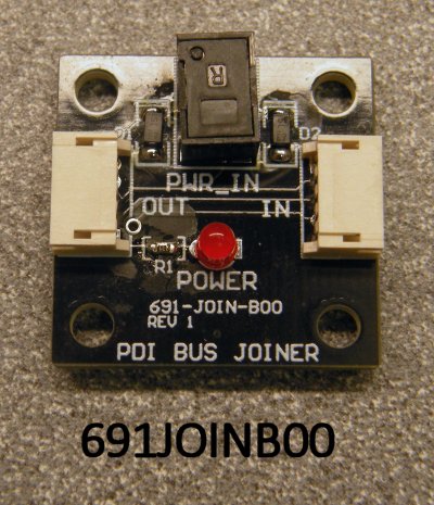
As always with this esteemed group, much helpful information offered freely.  I did know one can’t use two bases, but forgot that momentarily.  Thanks.  I’ve started looking for a source for the  Lionel 691-join-b00, so far none found.  I have a question, though.  If my daisy chained system were to include only ASC2’s, only using their latching relays to position Tortoise machines (whose motors are powered by a separate 12v supply independent of the LCS power supply of the chain), what is the current draw except momentary when one of the latching relays is set?  My understanding (limited it may be) is that latching relays draw no power once latched.

Since I may have other devices in the chain (as described by AmFlyer), if someone can suggest a current source for one or two of the 691-join-b00, will be grateful for that.

Don

Jim, I followed the link you provided, then did a triple take looking at the picture. It is the picture I took on my office carpet of one of my spare Joiners! I posted it here on the OGR Forum about a year ago. Apparently Lionel scraped it for use on their website. I wonder if OGR knows about this use of a picture?

I really do not mind, I am flattered Lionel thought my photo was good enough to sell their product. Here is a repost of my original picture.


IMG_3190

Attachments

Images (1)
  • IMG_3190

Don, the amperage draw per device I mentioned is just for the PDI cable for processing and passing on the command signals. It is unrelated to the control outputs. This amperage draw is listed in the device instruction manual. Some examples are ASC-2’s and BPC-2’s each draw 50ma. A sensor track is 15ma and an STM-2 is 35ma.

The resistance/foot of the PDI cables is relatively high. When we initially turned on the first PDI run with just 35 devices the voltage at the last device was 5V. This was back in 2016, Lionel’s California R&D group engaged with us and did a test of a partial mockup of my LCS. They recommended and placed the three powered joiners. As I recall the objective for 100% reliable operation was no device would see less than 10V.

I expanded the LCS system a year later to its current size and needed to add two more powered joiners.

Left out the big current hog, the WiFi module. Just idling it draws 30ma, but with iPads paired with it sending commands it draws up to 300ma.

Last edited by AmFlyer

Thanks, Tom.  After I posted, it occurred to me that the combined resistance of the tiny conductors in such cables, plus all of the low-cost (in materials) connectors involved, might also generate a small voltage drop even for the tiny currents needed to throw the relays.  I’ll probably have 23-24 ASC2’s and 3-4 BPC’s in my system.  I’ve read a substantial portion of the LCS thread, and gather I should have roughly one booster per 7 added devices beyond the first 7, to emulate your solution, with regulated 12v DC power to the boosters.  So with perhaps 28 devices, at least 3 boosters are needed.  Am I making sense of your information correctly?

Also, I’m going to begin watching Lionel’s Base3 YouTube videos.  Didn’t realize they had gone beyond the first 4 minute teaser video.

I will repost my LCS loop here to aid in the reply. The power supply for the LCS system can output 2A with only minor voltage sag, it seems to be well regulated. From a purely amperage supply view that power supply could serve 40 ASC-2's. 40x50ma=2A. Many LCS users put all their LCS devices on a central panel with 1' interconnecting PDI cables. This arrangement could likely power at least 30 ASC-2's with no powered Joiner since there is only 35' of PDI cable to introduce voltage drop.

My layout has each LCS component co-located with the devices it controls, so they are strung out around the entire layout. That is how I ended up with almost 250' of PDI cable and 5 powered Joiners. The advantage is no control wire crosses a module joint and the control wires are very short.

To directly answer your question, 7 devices is a good starting point for the first part of the daisy chain because those first PDI cables carry the load of the entire system. It should be possible to put more LCS devices between the powered Joiners at the end of the daisy chain. My system is very conservative for two reasons. First, each extra Joiner, regulator and 1' of PDI cable only added around $50. Second, the layout builder had to warrant the system and would rather spend an extra $100 of my money upfront to avoid flying a technician across country to fix an unreliable system at his cost under warranty. I approved this because I wanted to run trains, not wait for warranty service.


IMG_0999

Attachments

Images (1)
  • IMG_0999
Last edited by AmFlyer

One of the unknowns mentioned in a post was the amp capacity of the 3 LCS outputs on the Base3.  In Demos with Dave episode 17, first long Base3 demo including Cab2 and Cab 1L use, he explains the whole Base3 internal power supply is 5 amps, shared between all radio functions in use and the 3 LCS outputs, and he speculates with several locos in use plus a large system of LCS devices we may be pushing that 5 amps to its limits.  That suggests we will still need the inline boosters for our larger systems.

@Jim Sandman posted:

It seems as I type this they are available at Lionel.  Why not try there?

PCB / PDI BUS JOINER WITH POWER JACK (NO DISCOUNT) - 691JOINB00 (lionelsupport.com)

Thank you. Could not get this to come up on Lionel store site no matter the search term.  Your link did it.  Have ordered five against what may come.  Not knowing all my cable lengths yet, but knowing there will be at least 26 devices with a cable for each, and more if I decide to use more LCS control functions than I’m thinking now, hopefully this is a safe estimate.

Sounds like, from GRJ’s experience, perhaps I should be ordering a couple of spare ASC2’s so I’m not caught by the failure rate at a bad moment in layout construction and testing.

The decision whether to use the LCS iPad app for switch panels in local areas can come later, if I’m understanding it right.  Will I have to re-generate all 92-96 switch ID’s from scratch, or will it be possible to enter them within the app without affecting the memory already in my Base2/Cab2 or Base3/Cab of choice ?  Not clear about that.  Still not sure the added complexity will make things easier given my limited LCS control wants of a lot of switches and ~24 spur tracks for the BPC2’s.  

It’s a walkaround layout, with the engineer expected to look for the numbered signs at switches or on local elevated panels for hidden switches, and use the Cab 1L to throw them by number.  Each Tortoise will control a bicolor red/green LED standing near the points from the same current feeding the motor, its polarity controlling the color.  The LEDs will be in the elevated display panels for the small number of  hidden switches.  Given this method, the color can be set so green means “main” and red, “divert”, regardless of which is straight or curved for the turnout itself.

Don, I have spares of most everything electronic on my layout. That includes LCS components, relays, reverse loop controllers, current detectors, diodes and capacitors. So far two ASC-2's have failed. I would call the failure mode "soft", because it would not remember its programming when the power was turned off. When turning the layout on it took 5 button pushes to reprogram it but that got old. They were replaced. So far no other type of LCS component has failed. One reverse loop controller has failed, three relays and one diode have failed. Time period is seven years.

When my layout was built only the engines were programmed into the Base 2 so there was no issue assigning TMCC ID's. The way the ASC-2's work is that the lowest turnout number is entered, the ASC-2 auto assigns the remaining TMCC ID's for the rest of the turnouts connected to it.

I am attaching the first of three pages of my TMCC data base to demonstrate. Note LCS module 7, it has 4 Tortoise turnouts. I key in 27, the device gets the TMCC ID of 27 and 28, 29 and 30 are auto assigned. Note LCS module 8, it becomes TMCC ID 31, it only controls one Tortoise turnout. Modules 7 and 8 are in Latching sub-mode so they operate the stall motor Tortoise machines. Module 10 is in Momentary sub-mode  because turnout 34 uses a DZ-2500 surface mount. Modules 2,5&6 are in Accessory mode so they can control lighting and uncouplers.

I included a screen shot of the freight yard to show how these come together, there are a total of 7 of these screens for the total layout. There are also screens that just have the controlled items w/o the track plan.

The layout has small monuments at each turnout that show its number (TMCC ID.) Each turnout also has a red/green position indicator, these are essential. I included a picture that shows a view of the freight yard with these items visible.


IMG_5778IMG_0015IMG_5380IMG_5379IMG_2839

Attachments

Images (5)
  • IMG_5778
  • IMG_0015
  • IMG_5380
  • IMG_5379
  • IMG_2839
Last edited by AmFlyer

Thanks, Tom for the additional information and layout map.  My plan is same as yours, planning to locate ASC2 as close as possible to each group of 4 switches, so the wiring from ASC2 to switches is as short as possible and the traveling is done by the PDI cables.  I think I will power all the DC needs including the PDI boosters from local fullwave bridge rectifiers fed by one of my fixed AC accessory buses, available in 2v increments from 6v to 16v, so I can choose the one that produces the correct net as close to 12v DC as possible.  With that plan, will the powered PDI connectors need filtered DC, or is fullwave rectified DC OK without a filter?  Don’t know system requirement in that respect.

@cnwdon posted:


The decision whether to use the LCS iPad app for switch panels in local areas can come later, if I’m understanding it right.  Will I have to re-generate all 92-96 switch ID’s from scratch, or will it be possible to enter them within the app without affecting the memory already in my Base2/Cab2 or Base3/Cab of choice ?  Not clear about that.  

As you create your track plan on the LCS iPad app, you enter the IDs that you have already assigned to each turnout.  The track plan on the screen makes it very easy to identify and throw a turnout without memorizing or looking up the ID number.

It’s a walkaround layout, with the engineer expected to look for the numbered signs at switches or on local elevated panels for hidden switches, and use the Cab 1L to throw them by number.  Each Tortoise will control a bicolor red/green LED standing near the points from the same current feeding the motor, its polarity controlling the color.  The LEDs will be in the elevated display panels for the small number of  hidden switches.  Given this method, the color can be set so green means “main” and red, “divert”, regardless of which is straight or curved for the turnout itself.

I did a similar setup using a pair of Dwarf Signals at each turnout to indicate position.  The use of Tortoise machines makes this very easy.  The LCS iPad app indicates the turnout position as well.  While its position indication can get out of sync with the turnout position, I have not yet had this happen.

Bob

@AmFlyer posted:

Jim, I followed the link you provided, then did a triple take looking at the picture. It is the picture I took on my office carpet of one of my spare Joiners! I posted it here on the OGR Forum about a year ago. Apparently Lionel scraped it for use on their website. I wonder if OGR knows about this use of a picture?

I really do not mind, I am flattered Lionel thought my photo was good enough to sell their product. Here is a repost of my original picture.


IMG_3190

I'm pretty sure it's not the same picture.  The Lionel picture features an "R" on the power input your shows a "P".  The background and lighting is also different.

That being said, an incredible use of the LCS ipad App.  I sir salute you and am in awe.  Nice job!  I use it as well but nowhere to that extent.  I think it is an underrated app that folks just don't know enough about to make it useful to them.


Last edited by MartyE
@AmFlyer posted:

Good eye, Marty. I now also see a shadow covering the W and E in Power on my picture that is not on the Lionel picture.

The LCS is for sure a fantastic app. Lionel needs to put up on their site all the LCS details that used to be there and more.

In reality, I think the entire LCS line has suffered from lack of advertisement and promotion. We always tried to explain them during the Legacy Meeting when they came out but we were preaching to a small group.

I applaud @Dave Olson who created a LCS podium for use at York to demo LCS stuff but then Covid hit and Lionel stopped coming to York.  I still see it in the background of some of the "Demos with Dave" videos. Dave did say they were going to update the LCS page that used to be on the Lionel site when Base3 is released.

Again I am really impressed with what you did.  Someday when I go "permanent" I hope to do the same.

Last edited by MartyE

Marty, I never made it to York for one of those forums you hosted, but I did watch every video of them that was posted. Thanks for the compliment, going with just the LCS and no physical controls turned out to be the right decision. I have been operating this layout since 11/2016 and have never regretted that decision. I hope to be using the layout and LCS for many more years.

The promised Base3 has three LCS ports which, according to Lionel's comments, have circuit protection and presumably have the amps to power a suitable number of LCS modules.  We'll see.  The problem of voltage drop over long PDI runs remains so splicing lower-gauge wire in to PDI cables and use of the PDI power injectors may stil be necessary.

The large number of switches and ASC2s under discussion hints at pushing into the 1-99 address space limit for switches.  A discrete chain of ASC2s headed by a power injector and a WiFi in NOBASE mode can be controlled by the iPad LCS software.  Each iPad connects to only one of the WiFis at a time so the 1-99 address space can be overlapped on the discrete chains.  These isolated "switch groups" may suffice where the single Command Base doesn't have to control all the layout's switches.  One or more iPads can be configured to connect to and manage each switch group.

AmFlyer - thanks for posting images of your LCS test screens.  Great idea!

Tracker John, good point about the TMCC address limitations and possible solutions. My layout only has 45 turnouts so there was no issue, but as can be seen from the Test Turnouts page posted above only 41 TMCC addresses were used. The LCS mimic posted below of Mainline 1 shows three of the interchange turnouts, T39, T40 & T41 that are operated as a pair, each pair with a single TMCC ID. Sometimes every little bit helps.

What I thought I would use, but almost never do are the preset routes, the FIRE icons.


IMG_0011

Attachments

Images (1)
  • IMG_0011

Regarding the 12v “booster” PDI cable accessories: Is it correct that their ground (-) side should be in continuity with the layout’s AC common ground?  I ask because I think I want to take my existing 6v AC accessory bus and rededicate it to a 12v DC filtered-regulated supply that can serve multiple needs, mainly powering all the Tortoise machines but also these few PDI boosters.  Workable plan?

Don, I can only share how my layout is powered and wired. All track power is supplied by two ZW-L's. There are eight independent power districts, supplied by the eight output channels. Nothing else is powered from the ZW-L's. The powered LCS Joiners have their own dedicated DC power supply. There is also a 14VAC power supply for all the ASC-2's and BPC-2's. My layout is two rail, think American Flyer heritage. The turnouts and crossings have powered metal frogs so power to the frogs must be flipped when a turnout is thrown. Relays are used to do this, they have their own 12VDC power supply for the relay coils. The Tortoise motors and the DX-2500 coils have a dedicated 18VAC power supply. None of these power supplies have an AC common, or a DC (-), tied to any other power supply.

American Flyer never used track power for accessory power in S gauge. A few action cars used the Base Post rail via a metal wheel set for power return. The unfortunate reality is these cars will not work on layouts with reverse loops. There are 5 reverse loops in my track plan, each supplied from a reverse loop controller. That results in 20% of the track inside a reverse loop, the ZW-L U post can be connected to either rail, depending on the reverse loop controller position. All the accessories that touch track power, like the Dallee block occupancy detectors, must be wired through the reverse loop controllers if they are on reverse loop controlled track. The wiring for two rail can be more complicated than 3 rail. Generally in 2 rail there is no advantage to tying common power supply wires other than track power together.

In three rail I know some layouts are wired with shared commons. Not my area of expertise so hopefully someone else can help you.

Interesting, thanks, Tom.  As long as the (+) side of the 12v DC doesn’t get crossed with some other circuit, the shared “ground” for (-) side should not cause a problem.  Will make sure what is now the “hot” side bus wire of the now-6v AC bus is truly dead and isolated from all other hot buses before connecting the (+) 12v DC power supply, and then always make sure any wire that is DC (+) in the connected circuits remains isolated from other circuits or grounds.  It will then be it’s own circuit, even though the (-) side happens to be shared with the AC common ground system.  Choosing to make (-) in continuity with other grounds is just a handy convention, makes it easier to remember and stay consistent as other 12v DC loads are added.

Now have the 4-switch Tortoise groups chosen, ASC2 locations planned, and necessary PDI cable lengths ordered along with five 691-JOIN-B00’s.  Have a large regulated 12v DC supply recommended by Bill Bramlage already.  Ross switches not already here are ordered along with one more case of GG phantom tinplate for the yard to be added (that I didn’t think I needed, till I actually looked at all the second-hand track I thought was it!). If I’ve overlooked anything, hopefully someone will point it out :-)

I have 3 of the old BPC (not BPC2).  I’m not clear whether those will function with the current Layout Control System, or I need to buy 3 of the BPC2’s now to achieve that.  I could probably wire the BPC’s independent of the LCS to serve their spur track relay function, if not, but it would be nice to control them from a Legacy remote for convenience.

Too many details! Thanks for all the advice.

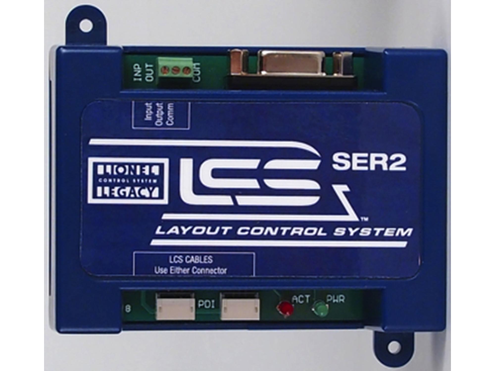
Looking at SER2 instructions and the old BPC instructions, both, it appears SER2 for my situation is effectively like adding a DB9 connector to the Base3, and then BPC’s (or other older TMCC devices like them) can be (maybe?) daisy-chained using just the one SER2 and one powered DB9 base connector.  The SER2 instructions only show one example of an older device, with a single ASC connected with 2 wires to the output of a SER2.  Is it necessary to have a SER2 for each older device, like my BPC’s, rather than being able to daisy chain the 2 connections to more than one (3 BPC’s, in my case)?

It also looks like a different powered base cable will be needed for the 3 Base3 LCS connectors, since what I have now is a DB9 powered connector for the 990.

Still a bit fuzzy. Thanks for the expertise, guys

I do not use the SER2 so I have no first hand knowledge. The original Lionel LCS example diagram has some information that may help. Lionel has deleted those LCS pages but searching on "Lionel LCS diagram" brings up several sites that have an image of it posted.

I am not sure what you mean by  a different powered Base cable for the Base 3 LCS outputs. They do not need a separate power supply as with the Base 2.

Yes, thanks, thinking the same thing.  I actually have five of them on the way from Lionel.  Overkill, unless I discover a bunch more things needing added to the chain, which is not impossible :-)

I’m trusting that those can be added into the chain just as readily with the self-powered Base3 chain, as if I were still using the 990 base and powered DB9 starter cable.  Would expect so.  I have only 3 old BPC’s, so the SER2 shouldn’t have trouble transmitting power from its place in the LCS daisy chain to just those three.  If so can add a booster upstream of the SER2.  Having done none of this, YET, I hope my understanding is at least close.

Wow, this is a big undertaking and if the ASC2’s are like the original ASC’s, BPC’s, you could daisy chain 13 ASC units, bringing up to 100 switches under your command, says the instruction manual. I have never operated all of my switches at once, however, I do have 7 Routes, via Lionel Legacy Cab 2 and the Cab 1L remotes. 9 switches in some routes. They work like dominoes, 1-2-3etc…you might contact Mike Reagan who used to own Train America Studios years ago. I think he is with TW TrainWorks. I use the BPC’s for 20 blocks. Good luck and keep us posted, very interesting thread. I do understand there’s a difference in the newer ASC2’s, but thought I would share this bit of knowledge. I have 40 switches, many connected to two. Switch 22 for example flips 2 at one push of the button. Happy Railroading Everyone IMG_8846IMG_8845

Attachments

Images (2)
  • IMG_8846
  • IMG_8845
Last edited by leapinlarry

Larry, thanks for your post.  FYI the difference with the ASC2, important for me, is its option for latching relay function so it can power stall-motor machines like Tortoise.  No doubt I’ll keep you posted as this project comes along.

GRJ, thanks for your reassuring comment.  I am glad for the three outputs from Base3.  I think that will make it easier to sort the routing for daisy chaining, not being limited to one chain.

The promised Base3 has three LCS ports which, according to Lionel's comments, have circuit protection and presumably have the amps to power a suitable number of LCS modules.  We'll see.  The problem of voltage drop over long PDI runs remains so splicing lower-gauge wire in to PDI cables and use of the PDI power injectors may stil be necessary.

The large number of switches and ASC2s under discussion hints at pushing into the 1-99 address space limit for switches.  A discrete chain of ASC2s headed by a power injector and a WiFi in NOBASE mode can be controlled by the iPad LCS software.  Each iPad connects to only one of the WiFis at a time so the 1-99 address space can be overlapped on the discrete chains.  These isolated "switch groups" may suffice where the single Command Base doesn't have to control all the layout's switches.  One or more iPads can be configured to connect to and manage each switch group.

AmFlyer - thanks for posting images of your LCS test screens.  Great idea!

The Switches are not limited to 99, the LCS system supports up to 250 switches.

jon

@cnwdon posted:

Larry, thanks for your post.  FYI the difference with the ASC2, important for me, is its option for latching relay function so it can power stall-motor machines like Tortoise.  No doubt I’ll keep you posted as this project comes along.

GRJ, thanks for your reassuring comment.  I am glad for the three outputs from Base3.  I think that will make it easier to sort the routing for daisy chaining, not being limited to one chain.

cnwDon, if you would like, I would be happy to have a phone call with you to answer any questions on LCS.

Add Reply

Post
×
×
×
×
Link copied to your clipboard.
×
×