There should be no wires to the outer rails of the cut tracks inside the blocks.
@DoubleDAZ good catch. I will check tomorrow. Easy fix if there are.
Just know I’m talking about the outside "rail", the one with all the cuts. That’s why most folks connect one rail and make cuts on the opposite rail. One rail has to be connected for the wheels to make the connection with the cut rail to trigger the signal.
@DoubleDAZ yeah, most people plan this out ahead of time. But, I am like Eric and do not do that. Lol! I understand the assignment. Easy check and fix. Sleep well, young man. I will update everyone tomorrow.
10-4. 🤣
@DoubleDAZ @Mark Boyce @mike g. Team, I just got home and Dave did in fact figure it out! I put a ton of drops on this little layout and there was ground drops on the outside rails in between the block. So, everything was setup properly - except that part....lol! Everything is working properly, now I can go practice my soldering. Appreciate everyones help, per usual! Happy modeling!
Wish me luck 🙃🙃🙃🙃🙃🥴
That's great news! Nicenqork Dave!
Don't forget to post a video!
Ken, that is great news!
Ken, that is great! I read through everything about an hour ago and am glad Dave came up with a suggestion that solved it.
Mark, I had thought about power, but thought I saw the lights working in the video. I was about to throw in the towel when Ken told me the lights didn't actually work like I thought I saw in the video. Then the only thing that had to be the answer was power drops in those blocks. If nothing else, we learned a lot about wiring signal lights. ![]()
Dave, yes we did learn about them. In all my years, I have never even looked into signaling or the wiring to make them work.
Yes, I saw a light too, but may have not been looking at the right place. I was like I have said to Kim about her mum even 40 years ago; Nan doesn’t know what she’s looking at! 🤦♂️
Here you guys go. Forgot to add to my reply...lol
Hey look at that, wonderful job and congratulations!
Are you able to walk all the way around the layout table?
@DoubleDAZ it is funny what you said about what we learned. I was really bummed because Atlas says their signals are plug play and easy to install. I was like, NOPE!!! LOL! But in retrospect, they actually were very easy except that part. They should have something in there about making sure there is no power in the block. I would think many people have power either in their switch or very near. Especially like my 4 switches. I cannot imagine there is no drop in others setup like mine. But, what do I know? Clearly not much 🥴
@mike g. , if I pull it out, yes.
So are you going to put a signal so you know what's on the part you can't walk around? Or can you atleast see all the way around it?
Ken, there should be a note for those new to the hobby. One of the diagrams does show power to one rail and cuts in the opposite rail, but a note would certainly help. I should have asked earlier how the track was wired. I made an assumption based on the size that there wouldn’t be that many power drops. Plus, the video made it look like it was working for a bit.
@DoubleDAZ @Mark Boyce @mike g. I am hoping I did it right. Not sure if you noticed, but when the loco made a loop around the inside loop but touched the outer loop the lights did nothing, but when it came around for the 2nd loop and on to main 1 it did turn red. I am guessing it is right as both axles do not land on main 1 at the same time, until that last lap? We will cross that bridge if there is an issue. Just thinking about when the kids come over. When I run 2 locomotives, I lock out the switches in proper position as the locos just go in circles...lol. although now with the double house I can do "operations on inside loop while running another loco on main 1. I just realized I can technically operate 3 locos on this little layout!
No worries, I think all of you guys did amazing in helping from afar!!! I am very impressed!! And appreciative!
It’s hard to diagnosis electrical issues from afar. I’m sure if any one of us could have been there, it would have been fixed earlier.
WOOHOO look at that your a railroad barron! If you ask me it just keeps getting better from here!
Once again Congratulations!-
Congratulations, Ken! It looks great!
@mike g. @DoubleDAZ @Mark Boyce I have a backdrop that i will put around the 160" 2 sides and you will be able to just look from the front while sitting and playing. That is why that is the only logical place for a signal. Yes, Mark I did not think about signaling until I saw some dwarfs online and then saw them in action on other people's layouts, to include the overhead red/green as well as seeing them in the wild, that I wanted to get them. Yes, this would have been easier from the beginning but to Dave's point, learning through troubleshooting is also good. My backdrop is from Larc Backdrops. Just waiting until I get the back half done - where the flats and behind house. Very little to do. Once I am working on the front half of scenery only, I will put the backdrop up.
Again, I truly appreciate all the help! As I tell my wife when I land an acting gig, I could not do it without you. I came to the forum for help and guidance 10 months ago and Dave was the only one who volunteered. People said just search the internet (which to this day ****es my off, because I found the fourm online through search 🤬) Everyone has an opinion but very really have helped like you guys have! Very appreciative! 💪🏾
You know Ken I think everyone has experienced that here. There is tons of folks willing to help and like me sometimes I dont chime in because I might not have the total answer. But working with you and Dave, Mark and after years of being on here it is wonderful to learn and help those who ask!
Congratulations and I will keep watching your build and YouTube channel!
@Mark Boyce @DoubleDAZ @mike g. are you home and better? 💪🏾
Good sights and sounds to close out the weekend. Inaugural signal run.
@mike g. I can get around the whole layout. The tunnel can be reached from the backside. I have a taller step ladder that allows me to reach over the 2 ft backdrop which is why I used flats on that end. That same ladder allows me to work from the front side and reach 3/4 of the layout from the front open area.
@Dntbsillynow posted:@DoubleDAZ @Mark Boyce @mike g. I am hoping I did it right. Not sure if you noticed, but when the loco made a loop around the inside loop but touched the outer loop the lights did nothing, but when it came around for the 2nd loop and on to main 1 it did turn red. I am guessing it is right as both axles do not land on main 1 at the same time, until that last lap? We will cross that bridge if there is an issue. Just thinking about when the kids come over. When I run 2 locomotives, I lock out the switches in proper position as the locos just go in circles...lol. although now with the double house I can do "operations on inside loop while running another loco on main 1. I just realized I can technically operate 3 locos on this little layout!
Ken, that is the correct operation given how things are connected. It turned red when the engine entered the block for signal 2. None of the switches are isolated, that’s why it could run through the switches to go around the inner loop without triggering the signal. However, like Mike was saying, that really isn’t the correct operation, the signal should turn red when an engine hits either of the bottom switches. Better yet, it should turn red whenever any of the 4 switches is thrown to cross between the loops. And, as Mike says, ideally it should stay red until the last car has passed.
BTW, do both switches get triggered together to cross between loops or do you have to trigger each one? I’m trying to think of how to wire things so the light changes when the switches are triggered.
Nice video Ken, keep up the good work! Just remember it's your build so build it to be fun for you and the kids!
@mike g. Yes! And ty! @DoubleDAZ what do I need to do to have that happen? I do not know how this stuff works, but I use logic to figure my way through life as I feel that is a good starting point in life. I was thinking the same thing, which is why I posed the question. My tiny knowledge of electrical setups made me think something was not quite right when it did not turn red. Just a quick follow-up to what you said about it should be red if any of the 4 switches has a train in it. When I am running 2 trains, there are moments when the inside loop loco is within the 4 switch area, but it does travel like this video as you know there is a straight line in inside loop, so both locomotives technically 2 can travel in that space at same time.
Ken, just to clarify. I believe Mike mentioned an engine moving from the inner loop to the outer loop. I said the signal should turn red when the engine hits the bottom switch or better yet whenever 2 of the switches are set for a crossing. Unfortunately, turning red when the engine hits the bottom switch doesn't really do any good realistically because the engine will already be interfering with the outer loop. You really need a way to turn the signal red when the switch is set for crossing regardless of where the engine is in the loop. This applies to both switches A&B as well as C&D.
Here's the normal setup with an engine on the inner loop.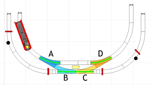
When you decide to cross between loops, you push the remote controller button(s) to set the A&B switches as shown. Realistically, the switches should work in tandem and ideally 1 button would set both switches. However, if the switches are configured for anti-derailing, then only switch A needs to be set and switch B will automatically get set when the engine hits it.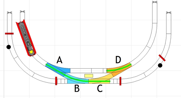
Once the engine passes through, the A&B switches should be reset.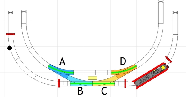
If the engine is on the outer loop, this time when you decide to cross between loops, you push the remote controller button(s) to set the C&D switches as shown. Again, ideally 1 button would set both switches and if the switches are configured for anti-derailing, then only switch C needs to be set and switch D will automatically get set when the engine hits it.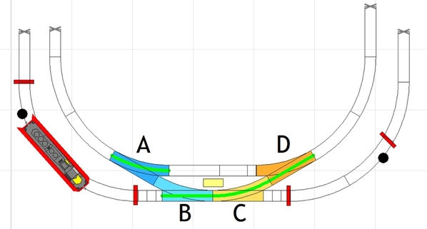
Again, once the engine passes through, the C&D switches should be reset.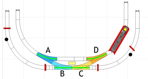
In this image, the top group shows how I think you have the remote controllers connected to the switch machines. Press the button for switch A to set the switch to go from the inner loop to the outer loop. When the engine hits switch B, the anti-derailing feature automatically sets switch B. If not, the button for switch B also needs to be pressed.
Now, I don't have Atlas switches, but I believe you can combine control using 1 remote controller simply by connecting the wires for both switches to the same remote control button. This is probably best done by connecting remote controller A to a terminal strip and then connecting both switch machines A&B to that, the same with the C controller and C&D machines.
And now, when to comes to the signal, I don't know if the wire from the Din can be added to both remote controller terminal strips, so that when 1 of the buttons is pushed, the light turns red. I think it can, but if the button is pressed too soon, the red-yellow-green cycle might complete before the engine gets there or passes all the way through. I don't know if just the momentary contact is enough to trigger the cycle or if the contact needs to last longer, like it does when the engine goes through the block. This can be tested by using a short wire to momentarily touch both rails in the block. My guess is it only needs a momentary contact, but I have no way to test my theory.
I only suggest this methodology because I don't see a way to create a block that can let an engine run around the loop and still be the trigger for the signal. In my mind, you'd have to power the rails in the block based on the position of the points. While that can probably be done, simply pressing a button seems easier.
However, I just realized that by pushing the button again to reset the switches will also start the signal cycle again. I think that can be avoided by using the 2nd remote controller with another terminal strip without the Din connection to reset the switches. Makes me wish I had this setup to play around with. ![]()
I'll have to see if they make a circuit board to that makes it all easier. Or maybe someone can tell me none of this will work and why, then I won't have to think about it again. ![]() Anyone???
Anyone???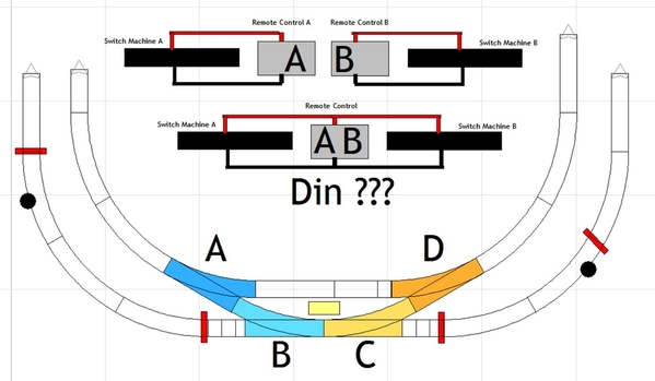
Attachments
@DoubleDAZ tyvm for looking into this. I think next week I will talk to Atlas. I have 2 boards and I think I can get it to work. Bill helped me with the part for the cheap signal and it worked, the signal was just trash. I have Atlas switches, they are anti-derail. I believe that is all they make in their switches. Sorry for the delay, I just got home from NYC filming Poker Face season 2 episode 7. Early call time tomorrow, heading to bed. Appreciate your work! Thanks, @Mark Boyce and @mike g.
@MarkB @DoubleDAZ @mike g. Doing a little running tonight. Only night off....
https://youtu.be/wVEPUdM8D8U?si=LtFuilmnKwUFiOTu
Looks good, Ken!
Nice Ken, it looks like Momma is having a good time! Good for you for sharing with her! LOL ![]()
@mike g. Yes! She really enjoyed it. The just picked tge cars up yesterday. She grew up with a Santa Fe set, which we have original boxes and set is pristine. I convinced her to just keep it tucked away and to buy a new set to run. This set is not new, but it is K-Line K4630-10503 set and it came with passenger's inside 😁
Great idea keeping the older one tucked away! Have fun!![]()
Looks like you might have to expand the layout so you can run trains together. 🤣
@DoubleDAZ@mike g.@Mark Boyce yep, that is why I asked to help with the o72 up above. We both love the Class A and big boy, plus she loves the #9 Shea She also likes the bigger Art Deco type steams with longer tender...We definitely need bigger curves....
@DoubleDAZ @mike g. @Mark Boyce it appears the L1 Mikado has a drive motor issue, it is/was not the track it appears. I contacted Lionel and they said to send it back as the driver motor seems faulty. Warranty....
Ken, I hope that turns out to be the problem. I just noticed that some of the images in my earlier post have disappeared. I’ll see if I still have them and fix the post.


